
Installation Instructions

P/N 315-095306FA-1Page 1 of 6
INSTALLATION INSTRUCTIONS AND WIRING FOR
P/N 8806
CONTROL MODULE
The 8806 Control Module interfaces polarity reversal
type of notification appliances to an Addressable
Device Circuit of a fire alarm control unit.
The 8806 supports Style Y (Class B) or Style Z
(Class A) Notification Appliance Circuit wiring.
Each module uses one address on the Address-
able Device Circuit. It does not require any me-
chanical address programming. Use the 8820
Programmer/Tester to program and test the
module. Up to 12 8806s can connect to each
Addressable Device Circuit. These modules must
be connected to the first 12 addresses on the
Addressable Device Circuit.
The power input for each 8806 comes from either
from an auxiliary power supply which is power
limited and UL listed for fire protective signaling
use. The 8806 maximum current is 1.5A at 24
VDC.
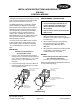
MOUNTING
The 8806 must be installed in a
UL Listed electrical box.
1. Use a 3
1
/2-inch deep, double gang electrical
switchbox or a 4-inch square electrical box that
is 2
1
/2 inches deep with either a 1
1
/2-inch deep
extension or a 1
1
/4 -inch deep plaster ring
extension.
2. Connect the field wiring. Insert the module into
the box and fasten the module and cover plate
(user supplied) to the box.
Figure 1
8806 Mounting
PROGRAMMING INSTRUCTIONS
CAUTION:
1. To prevent damage to the 8820, do not
connect modules to the 8820 until the
Addressable Device Circuit wiring is
disconnected.
2. Only one device must be connected to the
8820 at a time.
1. Plug the programming cable of the Faraday
8820 Programmer/Tester into the two-pin
receptacle on the module. (See wiring diagram
for location only.)
2. Set the system address for the module by
following the instructions in the 8820
Programmer/Tester Manual, P/N 315-
099214FA.
3. Record the device address on the label located
on the module. The module can now be
installed and wired to the system.
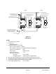
WIRING
Remove all system power before installa-
tion, first battery and then AC.
(To power up, connect AC first then battery.)
Refer to the appropriate wiring diagram and wire the
control module accordingly.
Faraday, LLC
805 South Maumee Street
Tecumseh, Michigan 49286
4” Square or Double Gang
Blank Cover Plate
(User Supplied)
Double Gang
Blank Cover Plate
(User Supplied)
4” Square Electrical Box,
2 1/2” Deep
(User Supplied)
Double Gang Electrical Box,
3 1/2” Deep
(User Supplied)
Module
1 1/2” Deep Extension Ring or
1 1/4” Deep Double Gang Plaster Ring
(User Supplied)
Module