
Installation Instructions

Siemens Industry, Inc.
Building Technologies Division
Florham Park, New Jersey 07932
P/N 315-699464FA-9 (v03-02-12) PAGE 1 OF 4
INSTALLATION INSTRUCTIONS AND WIRING FOR
CAT. NO. MPC-DACT DACT BOARD
The MPC-DACT Board is an optional module for the MPC-6000 and MPC-7000 Fire Alarm System
Control Units and the RND-2 Remote Network Display. The MPC-DACT (Digital Alarm Communicator
Transmitter) Board provides telephone line connections for communication with a DACR (Digital Alarm
Communicator Receiver). The DACT Board is mounted on the Main Board. The MPC-DACT Board
options are set through the control unit programming sequence.
PARTS SUPPLIED
1 MPC-DACT DACT Board
4 375-F943165 Spacers, 1”
1 899-G67197 Keps Nut, #6-32
1 315-699464FA Instruction Sheet
Step 1.) Installation is to be done by qualified personnel
who have thoroughly read and understood this
instruction sheet.
Step 2.) Disconnect BATTERY and AC prior to working on
equipment.
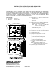
Step 3.) Mount DACT Board to the Main Board as shown,
using four spacers (P/N 375-F943165).
NOTE: Check to see that the header and
connectors are mated properly.
Step 4.) Attach ground wire as shown, using the nearest
main board mounting screw.
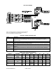
Step 5.) Attach conduit and run wires as required.
Step 6.) Connect wires to the fire alarm system control unit
as required.
Step 7.) Apply power to system.
Step 8.) Program for proper operation of functions.
a) Tech Level>>Outputs>Option Mods>DACT CFG
(Set DACT line and general configurations)
b) Tech Level>>Outputs>Option Mods>DACT ACCTS
(Set DACT account configurations)
c) Maint Level>>Disable/Enable>Outputs>DACT
>Enabled
NOTE: See Programmer’s Manual (P/N 315-
049403FA) for more details on programming.
Step 9.) Check for proper operation of functions.