
Installation Instructions

Siemens Building Technologies, Inc.
8 Fernwood Road, • Florham Park, NJ 07932
Tel: (973) 593-2600 • Fax: (973) 593-6670
Web: www.faradayfirealarms.com
P/N 315-049463FA-1 Page 1 of 2
Modules used in
MPC-6000 and MPC-700 Systems
are upgraded from time to time to improve their
operation or to add to their capabilities with new
features. These upgrades are sent to users as kits
which include a replacement IC(s) for the module
printed circuit board.
INSTALLATION GUIDELINES
Carefully follow the installation instructions below to
upgrade an MPC-6000 or MPC-7000 NAC proces-
sor on the main board, MPC7-DB main firmware on
the display board or NEM-1 NAC firmware.
CAUTION:
Electronic equipment is extremely vulnerable
to static discharge. Observe precautions for
handling static sensitive devices when
performing this upgrade.
To upgrade a module, remove the old IC(s) and
replace it with the new IC(s) from the kit as follows:
1. Notify the person in charge of the fire alarm
system (and the Fire Department if they are
connected to the MPC-6000 or MPC-7000) that
the control unit will be temporarily out of service
while the firmware upgrade is installed.
2. Upload your program to a PC if it is not already
saved.
3. Open the panel door and remove all power to
the control unit.
4. To upgrade the display board, you must uninstall
it from the front inner door. Disconnect the
ribbon cable and display cable from the display
PC board. Remove the screws and place them
to one side.
5. Locate the IC number and designation on the IC
in the upgrade kit.
6. On the PC board of the module being upgraded,
locate the IC. This IC has a label attached to the
top surface that indicates the IC number and the
software revision currently installed. Make certain
that the IC number on the module corresponds to
the IC number in the replacement kit.
7. Note where and how the IC is positioned.
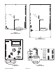
8. Remove the old IC(s) from its socket. (Refer to
Figure 1 for the location of U9 on the MPC-6000
main board, Figure 2 for the location of U9 on the
MPC-7000 main board, Figure 3 for the location
of U4 on the display board and Figure 4 for the
location of U1/U3 on the NEM-1.) Do this by lifting
one end of the IC slightly, then the other end.
Continue this process until the IC comes free.
Use a short, thin blade screwdriver for best
results.
9. Insert the new IC provided into the socket. Press
down firmly to seat the IC properly in the socket.
CAUTION:
Make sure the "U" cut in the new IC is positioned
as it was in the old IC (if appropriate). Check
that the IC is properly seated in the socket
and that all the IC pins are properly aligned
with the connector.
10. Reinstall the display board if it was removed using
the screws set aside in Step 4. Reconnect the
ribbon cable and display cable to the display PC
board. (Note: the ribbon cable is keyed and can
only be installed in one direction. DO NOT
FORCE it.)
11. Reconnect system power. Close the control unit
door and check operation of the system. The
control unit firmware upgrade is now complete.
INSTALLATION INSTRUCTIONS FOR UPGRADING FIRMWARE
MPC-UK