
Installation Instructions

Siemens Industry, Inc.
Building Technologies Division • Florham Park, NJ
Tel: (973) 593-2600 • Fax: (973) 593-6670
Web: www.faradayfirealarms.com
P/N 315-050563FA-0
Systems are upgraded from time to time to improve
their operation or to add to their capabilities with
new features.
The MPC-UK3 Chip (Rev. 7.06) is to be
used in MPC-6000 stand alone non-networked
systems only. The UK3 chip will correct field issues
with the MPC-DACT.
A new version of the CIS-4 program-
ming tool (Rev. 7.6.27) will be needed. It can be
downloaded from the Faraday Partner's web site
at www.faradayfirealarms.com.
INSTALLATION GUIDELINES
Carefully follow the installation instructions below to
upgrade the MPC-6000 main board firmware.
CAUTION:
Electronic equipment is extremely vulnerable
to static discharge. Observe precautions for
handling static sensitive devices when
performing this upgrade.
To upgrade a module, remove the old IC(s) and
replace it with the new IC(s) from the kit as follows:
1. Notify the person in charge of the fire alarm
system (and the Fire Department if they are
connected to the MPC-60000) that the control
unit will be temporarily out of service while the
firmware upgrade is installed.
2. Upload your program to a PC if it is not already
saved.
3. Open the panel door and remove all power to
the control unit.
4. To upgrade the MPC-UK3 chip, you must uninstall
the display board from the front inner door.
Disconnect the ribbon cable and display cable
from the display PC board. Remove the screws
and place them to one side.
5. Locate the IC number and designation on the IC in
the upgrade kit (Rev. 7.06).
6. On the display board of the module being
upgraded, locate the IC. This IC has a label
attached to the top surface that indicates the IC
number and the software revision currently
installed. Make certain that the IC number on the
module corresponds to the IC number in the
replacement kit.
7. Note where and how the IC is positioned.
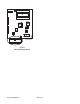
8. Remove the old IC(s) from its socket. (Refer to
Figure 1 for the location of U4 on the MPC6-DB2
display board.) Do this by lifting one end of the IC
slightly, then the other end. Continue this process
until the IC comes free. Use a short, thin blade
screwdriver for best results.
9. Insert the new IC provided into the socket. Press
down firmly to seat the IC properly in the socket.
CAUTION:
Make sure the "U" cut in the new IC is positioned
as it was in the old IC (if appropriate). Check
that the IC is properly seated in the socket
and that all the IC pins are properly aligned
with the connector.
10. Reinstall the display board using the screws set
aside in Step 4. Reconnect the ribbon cable and
display cable to the display PC board. (Note: the
ribbon cable is keyed and can only be installed in
one direction. DO NOT FORCE it.)
11. Reconnect system power. Close the control unit
door and check operation of the system. The
control unit firmware upgrade is now complete.
INSTALLATION INSTRUCTIONS FOR UPGRADING FIRMWARE
MPC-UK3