
Installation Instructions

P/N 315-049570FA-2 PAGE 1 OF 2
The MPC-REL Releasing module is an optional acces-
sory for the MPC-6000 Fire Alarm System Control Panel
which allows the panel to control Sprinkler Systems (Pre-
Action / Deluge), Water Spray Systems and Clean Agent
Fire Suppression Systems via approved solenoids (NFPA
750, NFPA 13 or NFPA 2001). The MPC-REL provides
two independent releasing circuits with a capacity of 1.5
amps each. This module is controlled by the panel. All of
the operating parameters are programmed through the
panel or the CIS-4 configuration tool.
The MPC-REL has four open collector circuits that can be
independently programmed on CIS-4 to activate for spe-
cific events. The open collector outputs are not supervised
and are rated at 24VDC @ 200mA. Separate 24VDC
terminals are provided on the open collector output con-
nector that is “current limited” to be used with the open
collector circuit.
A switch is provided to disable both of the releasing circuits
during service and maintenance. The switch is supervised
and will report as a supervisory event on the panel.
The MPC-REL mounts in the top of the enclosure on four
existing standoffs. Only one MPC-REL may be installed in
an MPC-6000. The MPC-REL requires an MPC-6000
Electronics Package 2 and an RPT-1 transformer which
mounts above the NPE-1 transformer(s).
RELEASING RATING:
Power Limited
Alarm Voltage: 24VDC, Filtered
Max Alarm Current: 1.5A / Releasing Circuit
For Special Application Only
OPEN COLLECTOR RATING:
Non-Power Limited
Alarm Voltage: 24VDC, Filtered
Max. Alarm Current: 200mA per circuit
The maximum cumulative output current of the
MPC-REL must not exceed 3A.
Max. Supervisory Current: 17mA
Installation Instructions for MPC-REL
Releasing Module
Siemens Building Technologies, Inc.
8 Fernwood Road
Florham Park, New Jersey 07932
906-220604 (4)
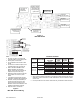
#6-32 x 1/4 SCREW
375-186167 (4)
#6-32 M/F SPACER (If required)
MPC-REL
RELEASING BOARD
ENCLOSURE
INSTALLATION
Step 1.) Installation is to be done by qualified person-
nel who have thoroughly read and understood
this instruction sheet.
Step 2.) Disconnect BATTERY and AC prior to work-
ing on equipment.
Step 3.) Mount the transformer in the top left hand side
of the enclosure.
Step 4.) Mount the MPC-REL board module using the
standoffs and screws provided.
Step 5.) Connect the transformer to the main board
and to the MPC-REL using the connectors
provided.
Step 6.) Connect wires from the terminals to the
solenoids as required.
Step 7.) Connect wires to the open collector outputs as
required.
Step 8.) Apply power to system.
Step 9.) Check for proper operation of functions.
Figure 1
Mounting of the MPC-REL in the MPC-6000
Enclosure