
Installation Instructions
PAGE 1 OF 2P/N 315-049480FA-2
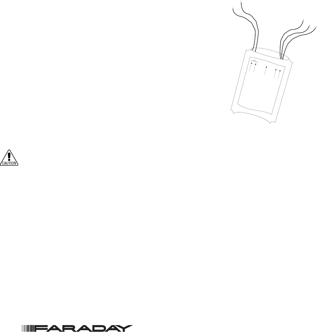
Figure 1
8701 Module
The 8701 contact monitoring module interfaces direct shorting devices to the
System’s Addressable Device Circuit.
The 8701 can monitor a normally open or closed dry contact and it can report
the status of the contact.
PROGRAMMING
Refer to Figure 1 to locate the red and black Addressable Device Circuit
wires of the 8701.
Connect the Addressable Device Circuit wires of the 8701 to the Model
8720 Programmer/Tester. Use the cable provided with the Programmer/
Tester and the two alligator clip to banana plug adapters provided.
To Prevent Damage To The 8720:
DO NOT connect an 8701 to the 8720 until all field wiring is removed from the red and black ad-
dressable device circuit wires of the 8701.
NOTE: Connection from the 8720 to the 8701 is not polarity sensitive. Refer to Figure 2 for the
proper connections to the control panel.
Follow the instructions in the 8720 Programmer/Tester Manual (P/N 315-033260FA) to program the
desired address into 8701.
Record the device address on the label located on the 8701. The 8701 can now be installed and wired to
the system.
WIRING
(Refer to Figure 2.) Refer to the wiring diagram and wire the addressable interface module accordingly.
NOTE: Recommended wire size: 18 AWG minimum, 14 AWG maximum
OR
G
BLK
L
IN
E
2
L
IN
E
1
G
RN
ORG RED
ALL CO
NN
ECTIONS
AR
E
POW
ER
LIM
ITED
EA
R
TH
G
N
D
8701
INSTALLATION INSTRUCTIONS AND WIRING FOR
CONTACT MONITORING MODULE
P/N 8701
Siemens Industry, Inc.
Building Technologies Division • Florham Park, NJ
Tel: (973) 593-2600 • Fax: (973) 593-6670
Web: www.faradayfirealarms.com