
User Manual

INSTALLATION INSTRUCTIONS FOR
MPC-6000, MPC-7000 AND RND-2 DISPLAY BOARDS
Installation is to be done by qualified personnel who
have thoroughly read and understood this instruction
sheet.
Step 1.) Upload the panel configuration to the CIS-4 software.
Step 2.) Disconnect BATTERY and AC prior to working on
equipment.
Step 3.) Remove cable connection from the keypad on the
Inner Front Plate to connector J3 on the Display
Board (P/N MPC(6/7)-DB, MPC6-DB2, RND2-DB or
RND2-DB2).
Step 4.) Remove the cable assembly (P/N 555-446055) from
connector J1 of the Display Board (P/N MPC(6/7)-
DB, MPC6-DB2, RND2-DB or RND2-DB2).
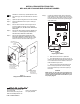
Step 5.) Remove the Display Board (P/N MPC(6/7)-DB,
MPC6-DB2, RND2-DB or RND2-DB2) from Inner
Front Plate Assembly by removing the four screws.
Place the screws to one side. Refer to Figure 1.
PLATE
906-220604 (4)
#6-32 x 1/4 SCREW
MPC-6000
ASS'Y
J3 - Keypad
Connection
Board
Display
to Main
J1 - Connection
Board
MPC-7000
showing Display
Board and Keypad
to Front Plate Ass'y
Board attached
showing Display
being attached
to Front Plate Ass'y
Figure 1
Display Board Removal/Installation
P/N 315-050139FA-0
Siemens Building Technologies, Inc.
8 Fernwood Road Phone: (973) 593-2600
Florham Park, New Jersey 07932 Fax: (973) 593-6670
Web: www.faradayfirealarms.com
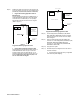
Step 6.) If replacing an RND-2 display board, transfer the
panel firmware IC (U4, located in the socket at the
lower right corner of the board as shown in Figure 2)
from the old board to the new one by following the
steps listed below.
U4
J2
R13
S1
U21
U2
U5
U6
J9
U12
J1
J3
Replace U4
U4
Figure 2
Replacing U4 on RND-2
a. Note where and how the IC is positioned.
b. Use a DIP extraction tool to remove U4 from its
socket on the new display board and then discard this
IC. If an extraction tool is not available, a short, thin
blade screwdriver may be used.
c. Remove U4 from the old display board. Insert
this IC into the proper socket on the new display
board. Press down firmly to seat the IC properly in
the socket.
CAUTION:
Make sure the "U" cut in the new IC is positioned as it
was in the old IC (if appropriate). Check that the IC is
properly seated in the socket and that all the IC pins
are properly aligned.