
User Manual

2
Step 7.) Reattach the cable connection from the keypad on the
Inner Front Plate to connector J3 on the Display Board
(P/N MPC(6/7)-DB, MPC6-DB2, RND2-DB or RND2-DB2).
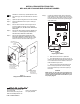
a. Keypad with releasing application LEDs for
MPC-6000 only
Align the keypad connector (P/N 215-649557FA) to J3
of the MPC6-DB2 as shown below. Insert the keypad
connector to the J3 header with pin 1 of J3 properly
aligned with the keypad connector until it is a tight fit.
(Refer to Figure 3.)
J3
J1
26-pin ribbon cable
connected to the
Main Board
Keyboard with
Releasing LEDs
connector
(P/N 215-649557FA)
Figure 3
Keypad with Releasing Application LEDs
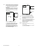
b. Keypad without releasing application LEDs
Align the keypad connector (P/N 215-649113FA) to J3
of the MPC6-DB2 as shown in Figure 4. Insert the
keypad connector to the J3 header with pin 1 of J3
properly aligned with the keypad connector until it is a
tight fit. Verify that pins 19-22 (last four pins) of J3
are not connected to the keypad.
LCD Contrast A djust
Backside of MPC6-DB2
LCD location
1
J3
J1
26-pin ribbon cable
connected to the
Main Board
Keyboard with no
Releasing LEDs
connector
(P/N 215-649113FA)
Figure 4
Keypad without Releasing Application LEDs
Step 8.) Secure Display Board (P/N MPC(6/7)-DB, MPC6-
DB2, RND2-DB or RND2-DB2) to Inner Front Plate
Assembly using the four screws removed in Step 5.
Refer to Figure 1.
Step 9.) Plug the Cable Assembly (P/N 555-446055) into
connector J1 of the Display Board (P/N MPC(6/7)-DB,
MPC6-DB2, RND2-DB or RND2-DB2) and to
connector J11 of the Main Board (P/N MPC6-MB,
MPC6-MB2 or MPC7-MB).
Step 10.) Apply power to system.
Step 11.) Download the panel configuration from the CIS-4 to
the panel and swap.
a. We recommend copying the primary configuration
to the secondary after swapping.
P/N 315-050139FA-0