Works-in-Progress package Version 2.0 For the SIEMENS Magnetom under VA21B Installation and User’s Guide NUMARIS/4A21 April 4th, 2003 Section of Medical Physics, University Hospital Freiburg, Germany Contact: Oliver Speck PhD, Hugstetterstr. 55, D 79106 Freiburg, email: oliver.speck@uniklinik-freiburg.
Multi-Echo EPI Table of Contents 1 Basic principles ................................................................................................. 3 1.1 Principle of Multi-Echo EPI ........................................................................... 3 1.2 Image contrast of Multi-Echo EPI ................................................................. 4 1.3 Processing options ....................................................................................... 4 1.4 References ...............
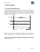
Multi-Echo EPI 1 Basic principles 1.1 Principle of Multi-Echo EPI The basic timing scheme of Multi-Echo EPI is shown in Figure 1. It is based on the original EPI sequence proposed by Mansfield (1). After a single RF-excitation, n complete EPI images are acquired in a single shot. The phase gradient is rewound to the original starting position after each echo-image to ensure identical k-space trajectories for all echo-images (2).
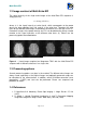
Multi-Echo EPI 1.2 Image contrast of Multi-Echo EPI The signal intensity of the single echo images of the Multi-Echo EPI sequence is simply given by: S = S 0 exp(−TE / T 2*) where S0 is the signal intensity at echo time 0, which corresponds to the proton density for long repetition times TR, and TE is the echo time. Therefore, the echo times of the different echo-images should be on the order or less than the tissue T2*.
Multi-Echo EPI 3. O. Speck, T. Ernst, L. Chang. Bi-exponential modeling of multi gradient echo data of the brain. Magn. Reson. Med. 45(6), 1116-1121 (2001) 4. O. Speck, J. Hennig. Motion Correction of Parametric fMRI Data from MultiSlice Single-Shot Multi-Echo Acquisitions, Magn. Reson. Med. 46(5): 10231027 (2001) 2 Software Installation Procedure 2.1 Installation The sequence consists of 5 files. The sequence file for the host, the sequence file for the MPCU and the ICE (EVA) program. Copy the sequence .
Multi-Echo EPI Page 6 of 9 Numaris/4 VA21B
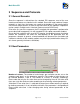
Multi-Echo EPI 3 Sequences and Protocols 3.1 General Remarks Since the sequence is derived from the standard EPI sequence, most of the user interface and features are identical to this method. Due to the large number of images created in a short time, the images are saved to the database in the mosaic format. One mosaic-image contains all slices of one echo time for one repetition. Repetitions can be saved in multiple series if desired (Contrast card or BOLD card).
Multi-Echo EPI Separate Correction: In the source code of the sequence card a new parameter ‘Separate Correction’ has been introduced. If this parameter is enabled (during compilation) each echo image is preceded by a new set of navigators used for the Nyquist ghost correction by the reconstruction. If the feature is disabled the same correction is used for all echo-images.
Multi-Echo EPI t-Test: The online t-test and display work as in the original EPI sequence. However, the t-test only works properly when motion correction is selected! Alternatively, T2*-Maps can be processed within the BOLD-card. 3.3 Remarks on reconstruction performance The number of images that can be acquired with the Multi-Echo EPI method is very high (up to 30 images per second for 64*64 matrix).