
Product Overview


Technical Instructions MXG461…U, MXF461…U Modulating Control Valves
Document Number CA1N4455E-P25 with Magnetic Actuators
May 8, 2009
Page 4 Siemens Building Technologies, Inc.
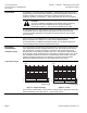
Table 2. Water Flow Chart.
Product
Number
Line
Size
(in)
ΔP
V100
PSI
C
VS
1 2 3 4 5 6 7 8 9 10 15 20 30 40 50
MXG461.15-0.6U 1/2 0.7 0.7 1 1.2 1.4 1.6 1.7 1.9 2.0 2.1 2.2 2.7 3.1 3.8 4.4 4.9
MXG461.15-1.5U 1/2 1.7 1.7 2.4 2.9 3.4 3.8 4.2 4.5 4.8 5.1 5.4 6.6 7.6 9.3 10.8 12
MXG461.15-30U 1/2 3.5 3.5 4.9 6.1 7 7.8 8.6 9.3 9.9 10.5 11 14 16 19 22 25
MXG461.20-50U 3/4 5.8 5.8 8.2 10 12 13 14 15 16 17 18 22 26 32 37 —
MXG461.25-8.0U 1 9.3 9.3 13 16 19 21 23 25 26 28 29 36 42 51 59 —
MXG461.32-12U 1-1/4 14 14 20 24 28 31 34 37 40 42 44 54 63 77 89 —
MXG461.40-20U 1-1/2 23 23 33 40 46 51 56 61 65 69 73 89 103 126 145 —
MXG461.50-30U 2 35 35 49 61 70 78 86 93 99 105 111 136 157 192 221 —
MXF461.65-50U 2-1/2 58 58 82 100 116 130 142 153 164 174 183 225 259 318 367 —
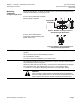
LED Indicators
The two-color LED display indicating operating status can be viewed by opening the
cover of the electronics module.
Table 3. LED Display.
LED Display Status Description
LED green On continuously Automatic mode: Auto (normal, no faults)
Flashing – Mechanically set to MANUAL
– Mechanically set to OFF
– Currently in auto-calibration mode
LED red On continuously – General fault
– General calibration fault
– Microcontroller fault
Flashing – Faulty 24 Vac supply (that is, too low)
LED Off – No 24 Vac supply
– Fault with electronics module
As a general rule, the LED can only assume the conditions in Table 3 (continuously red
or green, flashing red or green, or off).
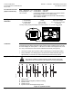
Mounting
Mounting and operating instructions are printed on the actuator and on the electronics
module.
The valve is suitable only for straight-through or three-way applications and may be
installed only in a mixing arrangement. In the case of the straight-through valve, strict
observance of the direction of flow is essential.
Do not mount with actuator below horizontal position.
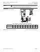
Access for Mounting
It is essential to maintain the specified minimum clearance above and to the side of the
actuator and/or electronics module for servicing, installing and heat dissipation:
• 1/2-inch to 1-1/4 inches = 4 inches
• 1-1/2 inches to 2-1/2 inches = 6 inches
Also see Dimensions.