
User Manual


SINAMICS G120 CU230P-2 Control Units
List Manual (LH9), 04/2014, A5E33838102B AA
641
3 Function diagrams
3.14 Signals and monitoring functions
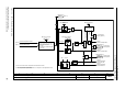
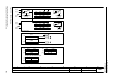
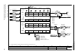
Fig. 3-130 8016 – Thermal monitoring, motor
- 8016 -
Function diagram
87654321
fp_8016_97_01.vsd
Signals and monitoring functions
G120 CU230P-2
07.04.2014 V4.7
Thermal monitoring, motor
T0
&
&
[6300.1], [6640.2]
p0610 = 1
-140 °C 250 °C
0
1
&
1
1
T0
0
1
<2>
1650
For KTY and "No sensor", temperature as defined in the model.
The relevant rated response temperature in °C depends on the temperature sensor
chosen by the motor manufacturer.
0 = No sensor
PTC alarm and time
KTY84
Bimetal NC contact alarm with
time step
KTY sensor type
(threshold not applicable for PTC)
Sensor type
Fault response
Suppress fault
with p0610 = 0
F07011
"Motor overtemperature"
A07910
"Motor overtemperature"
A07016
"Motor temperature
sensor fault, fault"
A07015
"Motor temperature
sensor fault alarm"
r0035
Mot temp [°C]
Mot_temp_sens type
0 ... 4
p0601 [D] (0)
1
Mod 2/KTY A thresh
p0604
Mod 1/2 threshold
p0605
Mot temp response
p0610
1 = Alarm motor
overtemperature
1 = Fault motor
overtemperature
via motor temperature model 2
KTY
<1>
PTC
I_max reduction
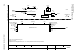
ZSW fault/alarm 2
r2135
r2135
.14
[2548.2]
ZSW fault/alarm 2
r2135
r2135
.12
[2548.2]
[8017.8]
1=
2=
4=
[8017.8]
<1>
<2>
via CU terminal (T1/T2)
[2201.1]
[8017.1]