
User Manual
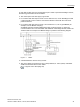
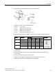

Table Of Contents
- PM230 Power Module, IP55
- Legal information - Warning notice system
- Table of contents
- 1 Changes in this manual
- 2 Fundamental safety instructions
- 3 Launch
- 4 Installing/mounting
- 5 Connecting
- 6 Service and maintenance
- 7 Technical data
- 7.1 Overload capability of the inverter
- 7.2 Cable cross-sections and tightening torques
- 7.3 Electromagnetic compatibility - Overview
- 7.4 Ambient conditions
- 7.5 General technical data
- 7.6 Specific technical data
- 7.7 Restrictions for special ambient conditions
- 7.8 Current reduction depending on pulse frequency
- 7.9 Electromagnetic compatibility of variable-speed drives
- 8 Spare parts and accessories
- A Appendix
- Index
Connecting
PM230 Power Module, IP55
Hardware Installation Manual, 12/2016, A5E35319202B AB
31
In order that an RCD does not unnecessarily trip as a result of operational leakage currents,
the following preconditions must be fulfilled:
● The neutral point of the line supply is grounded.
● For inverters with rated input currents ≤ 125 A referred to LO, use an RCCB type B with
a response limit current of 300 mA. Connect the RCCB in series with the overcurrent
protective devices.
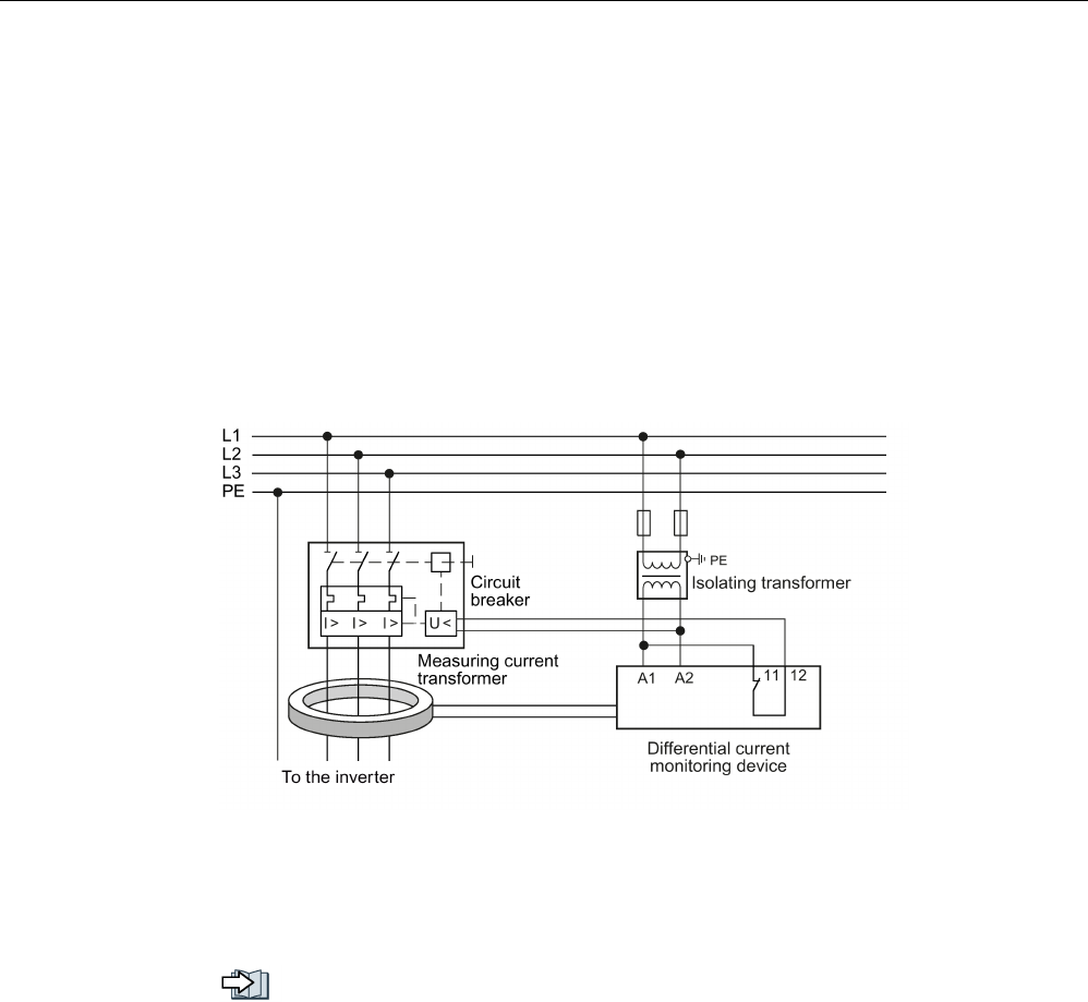
● For inverters with rated input currents> 125 A referred to LO, use a type B MRCD (for
example, from the Bender company).
An MRCD comprises an RCM (differential current monitoring device), a measuring
current transducer and a circuit breaker with additional undervoltage release, listed in the
Technical data. An example of an MRCD design is provided in the following diagram.
Figure 5-1 MRCD
● A dedicated RCD is used for every inverter.
● The motor cables are shorter than 50 m (164 ft) shielded, or 100 m (328 ft) unshielded.
Additional information about motor cables
Length of motor cable (Page 38)