
User Manual

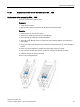
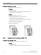
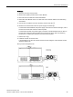
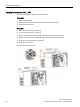

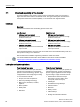
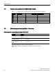
Table Of Contents
- PM230 Power Module, IP55
- Legal information - Warning notice system
- Table of contents
- 1 Changes in this manual
- 2 Fundamental safety instructions
- 3 Launch
- 4 Installing/mounting
- 5 Connecting
- 6 Service and maintenance
- 7 Technical data
- 7.1 Overload capability of the inverter
- 7.2 Cable cross-sections and tightening torques
- 7.3 Electromagnetic compatibility - Overview
- 7.4 Ambient conditions
- 7.5 General technical data
- 7.6 Specific technical data
- 7.7 Restrictions for special ambient conditions
- 7.8 Current reduction depending on pulse frequency
- 7.9 Electromagnetic compatibility of variable-speed drives
- 8 Spare parts and accessories
- A Appendix
- Index

Technical data
7.2 Cable cross-sections and tightening torques
PM230 Power Module, IP55
50 Hardware Installation Manual, 12/2016, A5E35319202B AB
7.2
Cable cross-sections and tightening torques
Table 7- 1 Connection types, maximum conductor cross-sections and tightening torques
Inverters
Connection
Cross-section / tightening torque
FSA
Terminal
1 … 2.5 mm
2
/ 0.5 Nm
18 … 14 AWG / 4.4 lbf in
FSB
Terminal 2.5 … 6 mm
2
/ 0.6 Nm 14 … 10 AWG, 5.3 lbf in
FSC
Terminal
6 …16 mm
2
/ 1.5 Nm
10 … 5 AWG / 13.3 lbf in
FSD
Cable lug 10 … 35 mm
2
/ 6 Nm 5 … 2 AWG / 53 lbf in
FSE
Cable lug
25 … 50 mm
2
/ 6 Nm
3 … 2 AWG / 53 lbf in
FSF
Cable lug
35 … 120 mm
2
/ 13 Nm
2 … 4/0 AWG, 115 lbf in
7.3
Electromagnetic compatibility - Overview
Electromagnetic compatibility according to EN61800-3
Property
Version
Interference immunity The inverters are suitable for use in First and Second Industrial Environ-
ments.
Interference emission
- First Environment
Category
C1
For in
verters with integrated radio interference suppression filter
acc. to C1
Interference emission
- Second Environ-
ment
Category
C2
For inverters with integrated radio interference suppression filter
acc. to C2
For further information, refer to the following Section:
Electromagnetic compatibility of variable-speed drives (Page 59).