
User Manual


Function diagrams
Explanations for the function diagrams
2-500
© Siemens AG 2011 All Rights Reserved
SINAMICS G120 Control Units CU230P-2 Parameter Manual (LH9), 06/2011
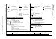
Fig. 2-1 1020 – Explanation of the symbols (Part 1)
- 1020 -
Function diagram
87654321
FP_1020_97_61.vsd
Explanations for the function diagrams
G120 CU230P-2
13.12.2010 V4.4
Explanation of the symbols (Part 1)
(Def)
pxxxx[y..z]
rxxxx[y..z]
(Def.y)
pxxxx[y..z]
rxxxx
rxxxx
rxxxx
[aaaa.b]
[cccc.d]
[aaaa.b]
pxxxx
[aaaa.b]
pxxxx[D]
pxxxx[C]
Monitoring parameter with
unit [Unit] and index range
[y..z] or data set [C/D]
Setting parameter with min/
max value and unit [Unit] data
set [C/D] and factory setting
(Def) *)
Connector input CI with
index range [y..z]
or data set [C/D]
and factory setting (Def) *)
Connector output CO with
unit [Unit] and with index
range [y..z]
Binector input BI with with
index range [y..z] or data set
[C/D] and factory setting.bit
number (Def)
Binector output BO
Connector/binector output CO/BO
The function diagrams are sub-divided into signal
paths 1...8 in order to facilitate orientation.
Text = Unique signal designation
aaaa = Signal goes to target diagram aaa
b = Signal goes to signal path b
Text = Unique signal designation
cccc = Signal comes from source diagram cccc
d = Signal comes from signal path d
pxxxx= Original parameter of signal
aaaa = Signal comes from source diagram
aaaa
b = Signal comes from signal path b
Parameter belongs to the
Command Data Set (CDS).
Parameter belongs to the Drive
Data Set (DDS).
Parameter name
[Unit]
rxxxx[y] or
rxxxx[y...z] or
rxxxx[y].ww or
rxxxx.ww
pxxxx[y] or
pxxxx[y...z] or
pxxxx[y].ww or
pxxxx.ww
from ... to
(xxxx[y].ww)
(Def)
(Def.w)
Parameter name (up to 18 characters)
[dimension unit]
"r" = monitoring parameter. These parameters are read-only
"xxxx" stands for the parameter number
"[y]" specifies the applicable index, "[y...z]" specifies the index range
".ww" specifies the bit number (e.g. 0...15).
"p" = setting parameter. These parameters can be changed.
"xxxx" stands for the parameter number,
"[y]" specifies the applicable index, "[y...z]" specifies the index range ".ww" specifies
the bit number (e.g. 0...15).
Value range.
Parameter number (xxxx) with Index number [y] and bit number .ww.
Factory setting.
Factory setting with bit number as prefix.
Diagram references for setting parameters that occur a multiple number of times.
[Function diagram number, signal path]
Parameters
Symbol Symbol Symbol
Symbol
Symbol
Symbol
Symbol
Symbol
Meaning Meaning Meaning
Meaning
Meaning
Meaning
Meaning
Meaning
Connectors Binectors
Connectors/binectors
Cross references between diagrams
Cross references for control bits
Information on parameters, binectors, connectors
Data sets
Parameter name
Parameter name [Unit]
Parameter name
Parameter name
Parameter name
Signal path
To "function diagram name" [aaaa.b] = binectors.
Text
Text
Parameter name [Unit]
rxxxx[y..z]
Parameter name
from ... to [Unit]
pxxxx[C/D] (Def)
Pre-assigned connectors
Parameter name
from ... to [Unit]
pxxxx[D] (Def)
Setting parameter with min/
max value and unit [Unit] data
set [D] and factory setting
(Def)
Symbol Meaning
For some parameters the value for the factory setting is calculated during commissioning for they are dependent on Power Module and motor (see Section 1.1.1 "Calculated").
*)