
User's Manual


Page 100 MultiRanger 100/200 – INSTRUCTION MANUAL 7ML19981FB06
mmmmm
Modbus Register Types
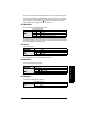
Discrete Inputs (R41,070)
This table shows the current status of the discrete inputs. Only register 41,070 is used.
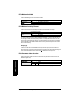
Relay Outputs (R41,080)
This table shows the current status of the relays. A reading of 0 means that the relay
function is not asserted and a 1 means that it is asserted. For example, a 1 for a pump
relay means that the pump is running.
Values are written to control a relay only if the Relay Control Function (P111) is set to
communications (65). See
Relay Function Codes (P111 Only)
on page 110.
mA Input (R41,090) [MR 200]
The mA input is scaled from 0 to 2,000 (0 to 20 mA multiplied by 100). P254 displays the
value of the input. This parameter is indexed by the input number.
mA Output (R41,110-41,111)
The mA output is scaled from 0 to 2,000 (0 to 20 mA multiplied by 100). This is displayed in
P911.
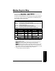
Pump Control (R41,400 – R41,474)
Only relays set for pump control (P111 = 50 to 52) are available. These registers have no
effect on relays programmed for other uses.
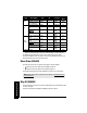
Pump ON Setpoint (R41,420 – R41,425)
The ON setpoint level (P112) for the referenced pump relay.
The setpoint is scaled from 0 to 10,000 (0 to 100% of span multiplied by 100). So 54.02% is
shown in the register as 5402.
Discrete Input Data Address
1 41,070, bit 1
2 41,070, bit 2
Relay Data Address
1
41,080, bit 1
2
41,080, bit 2
3
41,080, bit 3
4
41,080, bit 4
5
41,080, bit 5
6
41,080, bit 6