
User manual
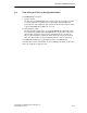

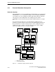
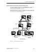
Table Of Contents
- Industrial Ethernet OSM/ESM Network Management
- Safety-Related Notices
- Contents
- Preface
- Introduction
- Important OSM/ESM Functions
- 2.1 Autonegotiation
- 2.2 Autocrossover
- 2.3 Transmission Rate and Duplicity
- 2.4 Factory Defaults and Protected Settings
- 2.5 Filtering Database (FDB Table)
- 2.6 Locked Ports
- 2.7 Mirroring
- 2.8 Traps
- 2.9 E-Mail Function
- 2.10 Event Log Table
- 2.11 Time of Day and Time- of - day Synchronization
- 2.12 Flow Control
- 2.13 BOOTP/DHCP
- 2.14 IP Configuration Using SIMATIC NET NCM PC, SIMATIC STEP 7 or the Primary Setup Tool
- 2.15 TELNET
- 2.16 Extended Redundant Configuration
- 2.17 Observer Function
- 2.18 Automatic Download of the Configuration
- Command Interpreter (CLI)
- Web-Based Management (WBM)
- 4.1 General Introduction
- 4.1.1 Restricted Functionality of the OSM/ESM Variants
- 4.2 Requirements
- 4.3 Connecting
- 4.4 Access Using Web-Based Management
- 4.5 User Interface of Web-Based Management
- 4.6 Management Menus
- 4.7 System
- 4.8 OSM/ESM Status
- 4.9 Agent Features
- 4.10 Switch Features
- 4.11 Port Status
- 4.12 Statistics Counters
- SNMP and RMON
- Upgrading/Downloading Software
- Notes on Troubleshooting
- Internet Browser Settings
- Connecting a PC with Hyperterminal to the Serial Port of the OSM/ ESM
- References
- Abbreviations/Acronyms
- Glossary
- Index
Important OSM/ESM Functions
2-18
Industrial Ethernet OSM/ESM Network Management
C79000-G8976-C137-08
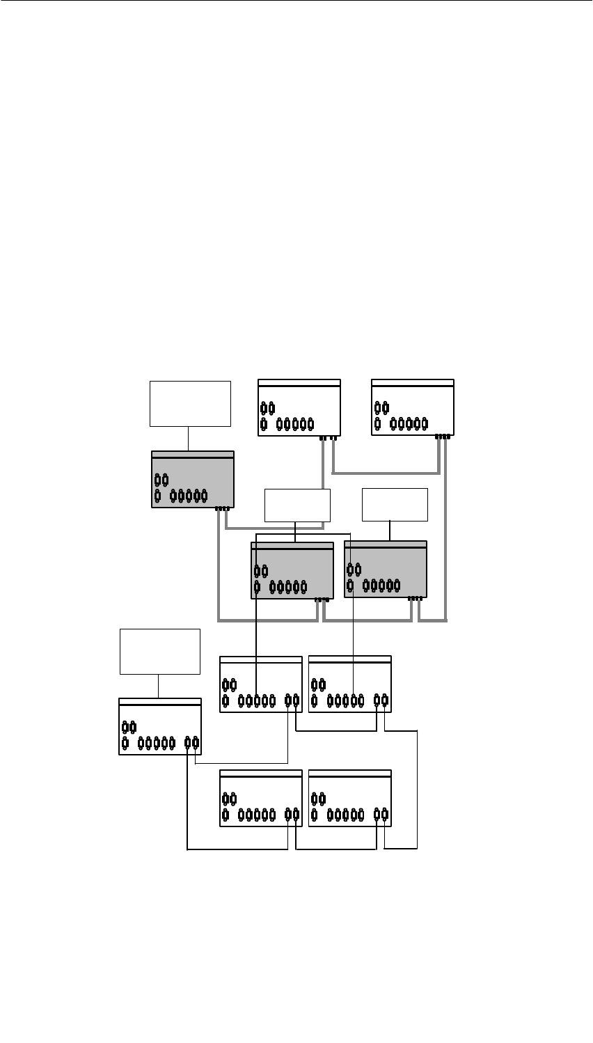
2.16 Extended Redundant Configuration
Redundant Coupling
With OSMs/ESMs (except for the OSM TP22 and ESM TP40), you can implement
redundant links, see /1/. A redundant coupling is created using two OSMs/ESMs,
one of which is set to the standby slave with the DIP switch (”Stby on”) while the
other operates as the standby master. The standby-sync ports of both
OSMs/ESMs are interconnected using an ITP XP standard cable 9/9, see Figure
2-1.
In the factory default setting, port 1 is monitored by the standby master. In
problem-free operation, data are transferred to the neighboring ring (network) via
this port while there is no data exchange via port 1 of the standby slave. If the
standby master fails or if there is a break on the link to port 1 of the standby
master, the standby slave takes over data exchange.
2
OSM
ITP 62
1 Fiber-optic cable (FO)
2 ITP XP standard cable 9/9
OSM in
RM mode
1
Port 1
Port 1
Standby
OSM
ITP 62
OSM
ITP 62
master
OSM ITP 62
OSM
ITP 62
1
1
1
1
ESM
ITP 80
2
ESM
ITP 80
2
ESM
ITP 80
ESM
ITP 80
ESM in
RM mode
2
2
2
2
2
2
Standby
slave
ESM
ITP 80
Figure 2-1 Redundant Coupling of Network Segments