
User manual
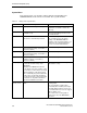
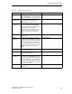
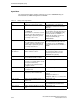
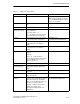
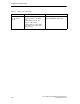
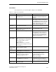
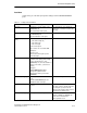
Table Of Contents
- Industrial Ethernet OSM/ESM Network Management
- Safety-Related Notices
- Contents
- Preface
- Introduction
- Important OSM/ESM Functions
- 2.1 Autonegotiation
- 2.2 Autocrossover
- 2.3 Transmission Rate and Duplicity
- 2.4 Factory Defaults and Protected Settings
- 2.5 Filtering Database (FDB Table)
- 2.6 Locked Ports
- 2.7 Mirroring
- 2.8 Traps
- 2.9 E-Mail Function
- 2.10 Event Log Table
- 2.11 Time of Day and Time- of - day Synchronization
- 2.12 Flow Control
- 2.13 BOOTP/DHCP
- 2.14 IP Configuration Using SIMATIC NET NCM PC, SIMATIC STEP 7 or the Primary Setup Tool
- 2.15 TELNET
- 2.16 Extended Redundant Configuration
- 2.17 Observer Function
- 2.18 Automatic Download of the Configuration
- Command Interpreter (CLI)
- Web-Based Management (WBM)
- 4.1 General Introduction
- 4.1.1 Restricted Functionality of the OSM/ESM Variants
- 4.2 Requirements
- 4.3 Connecting
- 4.4 Access Using Web-Based Management
- 4.5 User Interface of Web-Based Management
- 4.6 Management Menus
- 4.7 System
- 4.8 OSM/ESM Status
- 4.9 Agent Features
- 4.10 Switch Features
- 4.11 Port Status
- 4.12 Statistics Counters
- SNMP and RMON
- Upgrading/Downloading Software
- Notes on Troubleshooting
- Internet Browser Settings
- Connecting a PC with Hyperterminal to the Serial Port of the OSM/ ESM
- References
- Abbreviations/Acronyms
- Glossary
- Index

Command Interpreter (CLI)
3-10
Industrial Ethernet OSM/ESM Network Management
C79000-G8976-C137-08
OSM/ESM Menu
This menu includes special OSM/ESM settings, for example setting the fault mask.
Table 3-4 Settings in the OSM Menu
Command
Description Comment
info Displays the current values of the
OSM/ESM setting.
For explanations of the parameters,
see below or refer to the Glossary.
link <E | D> [ports] Enable | Disable link monitoring. Administrator only
Link monitoring is part of the fault
mask of the OSM/ESM, see /1/. The
signaling contact and the fault LED of
the OSM/ESM are activated when a
port whose link monitoring is
activated has no valid link.
power <E | D> [lines] Enable | Disable monitoring of the
power supply lines L1 and L2.
Example:
power E 1,2 enables monitoring for
both power supply lines.
Administrator only
Monitoring of the power supply lines
L1 and L2 is part of the fault mask of
the OSM/ESM, see /1/. The signaling
contact and fault LED are activated
when there is no voltage on a
monitored power supply line or when
the voltage is too low (less than
14 V).
standby <E | D> [ports] Enable | Disable standby ports see
Section 2.16.
This command specifies which ports
are standby ports.
Administrator only
Not for OSM TP22 and ESM TP40
counters Displays the results of the OSM/ESM
counters.
Meaning of the counters:
Changes to RM active state:
Indicates how often the OSM/ESM
acting as RM closed the ring.
Max. delay of RM test packets:
Indicates (in ms) the maximum delay
of the test packets sent by the RM.
(The delay should not exceed 50 ms.)
Changes to Standby active state:
Indicates how often a standby slave
took over the data exchange in a
redundant coupling (see 2.16
Signaled faults: Indicates how often
the signaling contact of the
OSM/ESM was activated, see /1/
resetc Resets the OSM/ESM counters. Administrator only