
User manual
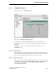
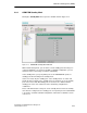


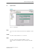
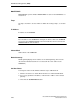
Table Of Contents
- Industrial Ethernet OSM/ESM Network Management
- Safety-Related Notices
- Contents
- Preface
- Introduction
- Important OSM/ESM Functions
- 2.1 Autonegotiation
- 2.2 Autocrossover
- 2.3 Transmission Rate and Duplicity
- 2.4 Factory Defaults and Protected Settings
- 2.5 Filtering Database (FDB Table)
- 2.6 Locked Ports
- 2.7 Mirroring
- 2.8 Traps
- 2.9 E-Mail Function
- 2.10 Event Log Table
- 2.11 Time of Day and Time- of - day Synchronization
- 2.12 Flow Control
- 2.13 BOOTP/DHCP
- 2.14 IP Configuration Using SIMATIC NET NCM PC, SIMATIC STEP 7 or the Primary Setup Tool
- 2.15 TELNET
- 2.16 Extended Redundant Configuration
- 2.17 Observer Function
- 2.18 Automatic Download of the Configuration
- Command Interpreter (CLI)
- Web-Based Management (WBM)
- 4.1 General Introduction
- 4.1.1 Restricted Functionality of the OSM/ESM Variants
- 4.2 Requirements
- 4.3 Connecting
- 4.4 Access Using Web-Based Management
- 4.5 User Interface of Web-Based Management
- 4.6 Management Menus
- 4.7 System
- 4.8 OSM/ESM Status
- 4.9 Agent Features
- 4.10 Switch Features
- 4.11 Port Status
- 4.12 Statistics Counters
- SNMP and RMON
- Upgrading/Downloading Software
- Notes on Troubleshooting
- Internet Browser Settings
- Connecting a PC with Hyperterminal to the Serial Port of the OSM/ ESM
- References
- Abbreviations/Acronyms
- Glossary
- Index
Web-Based Management (WBM)
4-25
Industrial Ethernet OSM/ESM Network Management
C79000-G8976-C137-08
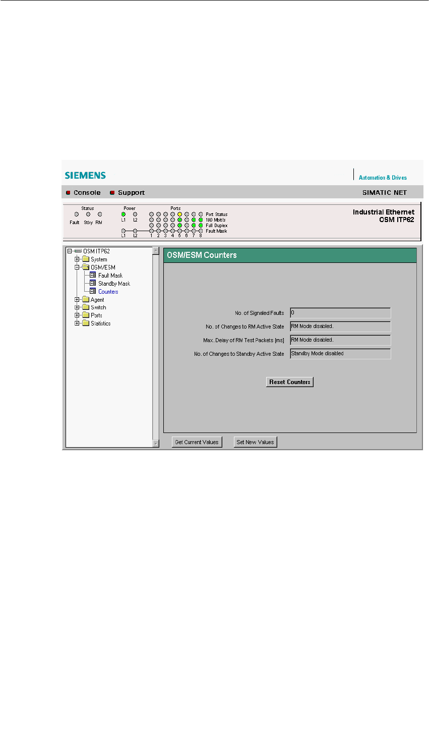
4.8.3 OSM/ESM Counters
Figure 4-14 shows the OSM/ESM Counters window. Using the OSM/ESM
counters, you can monitor whether and how often problems occurred during
operation (for example how often the signaling contact responded). The fault
counters are cleared when the power supply to the OSM/ESM is turned off or
when you click the Reset Counters button in the window.
Figure 4-14 OSM/ESM Counters Window
No. of Signaled Faults
This indicates how often the signaling contact of the OSM/ESM responded.
No. of Changes to RM Active State
(Only in the redundancy manager mode) This indicates how often the OSM/ESM
acting as the redundancy manager changed to the active state. This state is
adopted only when the RM has detected a break on the line of OSMs/ESMs
connected to the ring ports (port 7 and 8 of 8-port devices, port 3 and 4 of 4-port
devices). If the RM mode is disabled (DIP switch RM “off”), no value is displayed.