
User Manual


Detailed descriptions
17.1 Motherboard
SIMATIC Panel PC 877
17-16 Operating instructions, Release 07/2006, A5E00877780-01
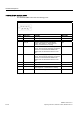
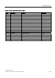
I/O front interface for operator panels, X44
This interface carries all signals required for the connection of operator panels in addition to
the display and USB interface. The maximum cable length is 50 cm at a USB data rate of 12
Mbps.
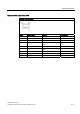
Pin No. Abbreviation Meaning Input/Output
1 GND Ground -
2 P12V Inverter voltage supply Output
3 BL_ON Backlight ON (5 V = ON) Output
4 P5V_fused +5 V (fused) Output
5 GND Ground -
6 P3V3_fused +3.3 V VCC (fused) Output
7 K_CLK Keyboard clock channel Output
8 K_DATA Keyboard data channel Input/Output
9 M_CLK Mouse clock channel Output
10 K_DATA Mouse data channel Input/Output
11 P5V_fused +5 V (fused) Output
12 USB_D1M USB data channel 1 Input/Output
13 USB_D1P USB data+, channel 1 Input/Output
14 GND Ground -
15 LCD_SEL0 Display type - Select signal 0 Input
16 LCD_SEL1 Display type - Select signal 1 Input
17 LCD_SEL2 Display type - Select signal 2 Input
18 LCD_SEL3 Display type - Select signal 3 Input
19 RESET_N Reset signal (active low) Input
20 Power button Power button function front Input
21 HD_LED HD LED, anode with 1 kW in series on the
motherboard
Output
22 DP_LED MPI/DP LED, anode via 1 kohm in series on the
motherboard
Output
23 Ethernet_LED Ethernet LED, anode with 1 kW in series on the
motherboard
Output
24 TEMP_ERR Temperature error LED, anode with 1 kW in series
on the motherboard
Output
25 RUN_R Watchdog error LED, anode with 1 kW in series on
the motherboard
Output
26 RUN_G Watchdog OK LED, anode with 1 kW in series on
the motherboard
Output