
Configuration Instructions


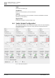


Configuration pages – Overview
'Audio Input Configuration'
6
A6V10429097_en--_e
111 | 219
'Averaging Time'
Defines the measurement cycle time. A larger number means more stable AVC
algorithm. However, for a long duration, the system will need more time to react on
noise level changes.
'Feedback Factor'
This value is used for signal feedback of the configured output. A large feedback
factor means that most of the level of the output is subtracted from the feedback
input level. So it is quite noisy.
'Show RMS'
Level meter Input 1 and 2 display measured RMS values to observe the AVC
calculation behavior.
6.2.7 Test Signal settings
You configure the characteristic of the test signal on the 'Test Signal settings' tab.
The characteristic of the test signal is used in audio input and audio output settings
to configure a specific channel/output.
The setting on this tab is also used to configure the generated sound of the
software buzzer. Also see 'Einstellung des akustischen Signals' in chapter 'Error
Logging, EN 54-16 & RSL [➙ 125]'.
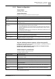
Fig. 66: Test Signal settings
Type
Choose a waveform to be generated: 'Sinus Wave' or 'White Noise'.
Frequency
If the waveform is set to sine, specify the target frequency too.
Gain
Adjust the level of the output signal.