
Configuration Instructions


Hardware specific configuration
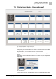
'Digital Input Mode – Regular Keypad'
7
144 | 219
A6V10429097_en--_e
Fig. 95: 'Customize paper strips' button
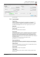
7.3.1 'Regular Modes'
'Push Button'
The selected input is configured as a push button that will control the green LED
for as long as the button remains pressed. Make use of this function in combination
with macros or digital outputs, to create a user defined behaviour of the call station.
'Switch L>H'
Only usable with macros for special settings. The corresponding green LED is
activated each time the button is pressed. This makes it possible to implement a
toggle function for the LED state.
'Switch H>L'
No special usage. The corresponding LED is not controlled.
'Second button' (for alarm calls)
This is a safety feature to prevent a call station alarm being triggered
unintentionally. Buttons which are configured with the 'SECOND_REQUIRED' flag
can only be triggered if the 'Second Button' is pressed at the same
time.
'Disable Keypad' button
Usable to lock the whole keypad. All other keys except this one are disabled
User could activate the lock by press this button. The corresponding LED signals
the actual state (RED = button lock activated). A repeated press deactivates the
keypad lock.
'Mode Switch'
Switch to toggle between Normal Mode and Elevated Mode. Elevated Mode could
be used to process alternative macros.
'Macro Mode'
This mode can be used to process macros, see chapter 'Using keypad macros
[➙ 90]'.
Macros could be used to trigger events by pressing or releasing a configured
button on the keypad.