
Configuration Instructions


Hardware specific configuration
'Logic Inputs – Connector'
7
A6V10429097_en--_e
149 | 219
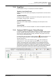
7.5 'Logic Inputs – Connector'
This configuration window is used to set the behaviour of the logic inputs.
Fig. 98: 'Logic Inputs – Connector' page
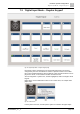
Each input is able to handle a different task. A selection of parameters is available
for each function (see tables).
Fig. 99: Logic input example
DI1
Mains failure
DI2
Battery failure
DI3 and DI4
Use of PT2002 with PTO2009 (2x
DC 24 V feed). Always set 'used for
logging'.
Function
Description
'Test & Quit Key'
Used for indication board. Manual Silencing of faults for audible indication of
faults (buzzer). Also used for silencing the voice alarm condition.
'GP' flag:
● If set, then all enabled outputs should be tested
● If not set, only specific outputs should be tested
– GP_OUT
– System Fault
– System Fault Buzzer
– System Variable with SysVarID=5 (voice alarm)
– System Variable with SysVarID=6 (silence alarm)
'Alarm Start'
A positive edge on the corresponding input starts an alarm. Same parameters
as 'Start/Stop'.
'Alarm Stop'
A positive edge on the corresponding input stops an alarm.
'GP' flag:
● If set, then all zones are deselected
● If not set, then no additional action is taken