
Installation Instructions

Connect external components
Call station PT2009-A1
7
110 | 122
A6V11899867_en--_a
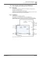
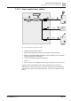
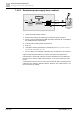
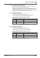
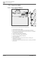
7.5.3 Connect to a cabinet
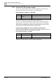
7.5.3.1 Power supply PT2009-A1
Fig. 59: Daisy chain wiring of multiple PT2009-A1 in the standard use case
1
Cerberus PACE Compact cabinet
2
External 'Desk call station (RS485, 8+1)' PT2009-A1 with accessories
3
DC/DC converter 'MeanWell SD-50B-24 DC/DC' PCA2011-A1 or 'MeanWell
SD-100B-24 DC/DC' PCA2018-A1
4
'Ground fault monitoring (24V)' PCA2001-A1
5
'ICPDAS I-7510 (RS485, isolated)' PNA2009-A1
6
'Call station interface (RS485)' PTO2008-A1
7
Wiring to PTO2008-A1
8
Copper Ethernet cable (CAT5) with RJ45 connector, connecting one
PTO2008-A1 to PT2009-A1
9
Copper Ethernet cable (CAT5) with RJ45 connector, connecting one PT2009-
A1 to the next
DC/DC
PCA2011
PCA2018
DC 24 V
Cabinet
PTO2008
RS485
intern
RS485 isol
PNA2009
Fuse
1
1
13
14
15
16
17 18
19
Ground Fault
PCA2001
CAT5
CAT5
1
2
1
2
12
RS485
Interf
Audio Out
Audio In
19
CAT5
PT2009
PT2009
PT2009