
Installation Instructions

Mounting/Installation
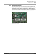
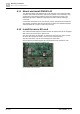
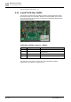
Mount and install PN1002-A1
4
A6V11899867_en--_a
47 | 122
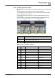
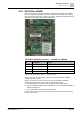
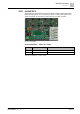
Single wire connector - 'CN1'
Pin
Description
Remark
1
Signal out +
Analog audio out +
2
Signal out -
Analog audio out -
3
24 V
Isolated 24 V
4
D-
Isolated RS485 data -
5
D+
Isolated RS485 data +
6
GND
GND of isolated 24 V
7
Signal in +
Analog audio in +
8
Signal in -
Analog audio in -
Table 17: PN1002-A1 single wire connector - 'CN1'
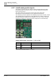
In case twisted pair cables are used, ensure that corresponding signals are
connected to the twisted pair wire, e.g. 24 V and GND, D- and D+ in the twisted
pair wire.
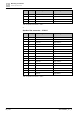
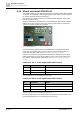
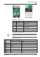
RJ45 connector - 'J4'
Pin
Description
Remark: when used in a 2x4 wire cable
CAT5 according to T568B
Fire alarm cables color code according to
VDE0815
1
Signal out +
White/orange
Grey
2
Signal out -
Orange
Yellow
3
24 V
White/green
Brown
4
D-
Blue
Red
5
D+
White/blue
Blue
6
GND
Green
Green
7
Signal in +
White/brown
White
8
Signal in -
Brown
Black