
Mounting Instructions
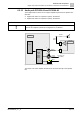


Install internal components
Digital audio matrix PC2003-A1
6
A6V10430579_en--_b
53 | 173
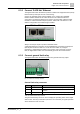
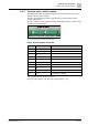
6.3.2 Connect 'PACE-Net' Ethernet
The digital audio matrix PC2003-A1 provides 2 'PACE-Net' copper Ethernet (CAT5)
RJ45 sockets (A and B) at the rear of the housing.
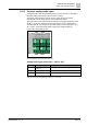
Connect an 'Ethernet switch (2x4/2)' PN2001-A1 or a 'Planet IGS-10020MT
Ethernet Switch' PN2005-A1 to extend the amount of 'PACE-Net' Ethernet
connections. The Ethernet switches are used to connect further Cerberus PACE
modular or Cerberus PACE Compact systems, 'PACE-Net' call stations or a PC
with the configuration tool 'PACE-Design' installed.
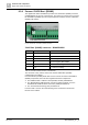
Fig. 26: PC2003-A1 network connector
Always connect port A (ETH A) with an Ethernet switch.
A redundant Ethernet connection can be established by connecting socket port B
(ETH B) with an Ethernet switch. It can be the same switch or, for higher
redundancy, another Ethernet switch in the system. If the connection on port A
fails, the digital audio matrix uses automatically port B for the communication.
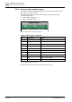
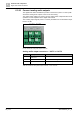
6.3.3 Connect general fault relay
The digital audio matrix PC2003-A1 provide one general fault relay output.
Fig. 27: PC2003-A1 fault relay connector
General fault relay connector
Pin
Designator
Connection
1
NC
Connected to C if fault occurs (relay released)
2
C
Common
3
NO
Connected to C in regular mode (relay active)
Table 14: PC2003-A1 fault relay connector
The general fault relay contact is used to display the operating status of the digital
audio matrix. The relay is activated (NO and C are connected) in regular operation
and is released in case of a fault.
ETH B ETH A
1
Fault