
Mounting Instructions


Install internal components
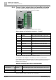
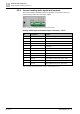
Power amplifier (4x150W) PV2003-A1
6
82 | 173
A6V10430579_en--_b
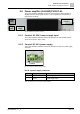
6.8.4 Connect status output relays and amplifier activation
The 'Power amplifier (4x150W)' PV2003-A1 provides one connect ('Control') to
report status of the amplifier and to activate the amplifier.
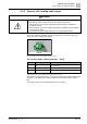
Fig. 60: PV2003-A1 status output relays and amplifier activation connector
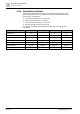
Status output and activation connector - 'Control'
Pin
Description
Remark
1
CH A/B ok
Relay output channel A/B ok, open: fault
2
CH A/B ok
Relay output channel A/B ok, open: fault
3
CH C/D ok
Relay output channel C/D ok, open: fault
4
CH C/D ok
Relay output channel C/D ok, open: fault
5
DC 24 V ok
Relay output DC 24 V ok, open: fault
6
DC 24 V ok
Relay output DC 24 V ok, open: fault
7
AC 230 V ok
Relay output AC 230 V ok, open: fault
8
AC 230 V ok
Relay output AC 230 V ok, open: fault
9
CH A-D on +
Activate channels A to D
10
CH A-D on -
Apply 12...24 V between pin 9 and 10
11
Br. A-D on +
Activates channels A to D in the bridge mode
12
Br. A-D on -
Apply 12...24 V between pin 11 and 12
Table 40: PV2003-A1 Status output and activation connector - 'Control'
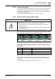
The activation of the amplifiers is controlled by the 'Auto on' potentiometer.
Each amplifier actives by themselves when an analog audio signal is present at its
input. The threshold to activate the amplifier can be set with the potentiometer
between 7 mV to 300 mV.
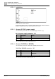
Amplifier activation with 'Auto on' potentiometer
Position
Description
Remark
Turn to max left
Remote on
Activate with inputs of the 'control' connector pins 9-10 or 11-12
In the middle
Auto on
Activates when signal is present
Turn to max right
Always on
Amplifier is always active
Table 41: PV2003-A1 amplifier activation with 'Auto on' potentiometer
1
C
o
n
t
r
o
l
12
Link 1
Link 2