
Configuration Instructions

System configuration
Using logic operations
5
96 | 219
A6V10429097_en--_e
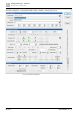
5.20 Using logic operations
A typical use case will be the need to switch a digital output, dependent of the zone
selection of a callstation.
The following example shows how an output is configured if zones 1 and 2 are
selected and the talk key is pressed.
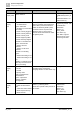
1. Activate the “Enabled” checkbox
2. Set the Function to “Keypad Led”
3. Set the “of Station” to the callstation station id
4. Right mouse button on the field led index field (default value = 1) and point to
the “Talk Key”
Configure two additional outputs which will point to “Zone 1” and “Zone 2” keys.
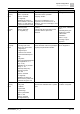
The digital outputs 1, 2, and 3 can now be used to display this status information:
1. Activate the “Enabled” checkbox
2. Set the Function to “Logic Operation Outputs”
3. Set the Led Mode to “AND”
4. Set the Audio Out/In to '0' (inputs/outputs 1 to 8 are addressed).
5. Set 'Input/SysVarID/Feed/Level/Led' to 7, i.e., the BCD-coded representation of
the first three outputs (OUT 1=1, 2=2, 3=4, 4= 8, 5=16, 6=32, 7=64) , 1 + 2 + 4
= 7.
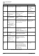
This procedure also works for digital inputs.