Cerberus PACE Accessories and options PCA20xx-A1, PCIO2001-A1, PCO2001-A1, PNA20xx-A1 Accessories and optional components for the EN 54-16-certified Cerberus PACE digital multi-channel audio system.
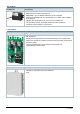
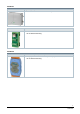
Use Call stations / operating terminals Ground fault monitoring (24V) PCA2001-A1 The ground fault monitoring (24 V) PCA2001-A1 is a module for monitoring 24 V lines outside of the system cabinets for supplying remote system components (e.g., call stations). It measures the resistance of both wires in the lines to the protective conductor (PE). According to the corresponding standard, a ground fault is detected when a resistance of <50 kOhm is measured to the protective conductor.
Automatic volume control The 'Automatic Volume Control' (AVC) function is used if background noise can be expected to fluctuate a lot, such as on train platforms and in airports and shopping malls. The AVC function is required as a way of adjusting the sound level of the audio signal to suit the current situation in the event of huge fluctuations in background noise. This ensures that the wanted signal is always louder than any background noise so that it will be possible to understand what is being said.
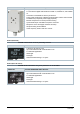
Loop isolators Loop isolator (100V) PCA2005-A1 The loop isolator (100 V) PCA2005-A1 is an isolating element in accordance with EN 54-17 for use in a 100 V speaker line. The isolator rapidly detects and isolates short-circuits affecting the line. It monitors the speaker line connected to the loop isolator for open lines and short-circuits. The status of the PCA2005-A1 is shown on an optical display. Two-pole standard wires are used as cables for the speaker loop.
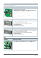
Features and Functions Call stations / operating terminals PCA2001-A1 'Ground fault monitoring (24V)' ● ● ● ● ● ● ● PCA2011-A1 'MeanWell SD-50B-24 DC/DC' ● ● ● ● ● ● PCA2018-A1 Monitoring of the DC 24 V line for ground faults Used with remote system components (Required when the 24 V line exits the system cabinet to supply energy to components such as the fire brigade microphone) Fault message via relay changeover contact (Fault / Okay) Fault indicated via LED on module Switch to a lower sensitivity o
I/O interfaces PCIO2001-A1 'Input/Output extension (digital 16)' ● ● ● ● ● ● ● PCO2001-A1 For use with the digital audio matrices PC2001-A1, PC2002-A1, PC2003-A1, PC2005-A1 and PC2006-A1 Communication via 'PACE-Bus' RS485 or RS232 interfaces Extends a digital audio matrix by additional 16 digital outputs Outputs are electrically isolated Extends a digital audio matrix by additional 16 digital inputs Extends a digital audio matrix by additional 8 analog inputs Provides a 'PACE-Bus' RS232 interface to comm
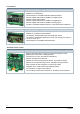
PCA2007-A1 'Automated volume control microphone' ● ● ● ● ● ● ● ● ● Supports automatic volume control to suit levels of background noise For use with the digital audio matrices PC2001-A1, PC2003-A1, and PC2005A1 Connection to PCA2008-A1 with a 3-pin terminal Power supply via phantom voltage through automatic volume control module PCA2008-A1 (no separate power supply required) Electret microphone in an IP54 protective housing Symmetrical output: selectable microphone / line level Microphone or line level (h
EOL modules PCA2004-A1 'EOL3 (active)' ● ● ● ● ● ● ● Monitoring the speaker line for open lines and short-circuits Monitoring in accordance with EN 54-16 Addressable: up to 16 different addresses can be configured Addressing compatible with any structure with up to 16 line ends, in addition to the stub line Reliable cable break detection in any branch of a speaker line No other wiring needed; works with standard two-wire speaker line No need to route line back to control panel Loop isolators PCA2005-A1
PACE-Net PNA2007-A1 'Repeater (CAT5)' ● PNA2008-A1 Extension of 100 Mbit/sec Ethernet line by 100 m 'Camdenboss RJ45 Interface' ● ● Interface from RJ45 connector to screw terminals 35 mm DIN rail mounting PACE-Bus PNA2009-A1 'ICPDAS I-7510 (RS485, isolated)' ● ● Smart Infrastructure 2-way optical isolated 'PACE-Bus' (RS-485) repeater 35 mm DIN rail mounting 9 A6V10430563_en--_b 2020-06-30
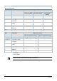
Type Overview Device combinations Type Designation Digital audio matrix PC2001-A1 Digital PC2002-A1 Digital audio matrix (4/4/4) audio matrix (0/4/4) PC2003-A1 Digital audio matrix (4/4/16) PCA2004-A1 EOL3 (active) ● ● ● PCA2005-A1 Loop isolator (100V) – – ● PCA2007-A1 Automated volume control microphone ● – ● PCA2008-A1 Automated volume control module ● – ● PCA2014-A1 Backup extension PC2003 – – ● PCIO2001-A1 Input/Output extension (digital 16) ● ● ● PCO2001-A1 Output exte
Order numbers Type Designation Order number ATP AF2GUD-2*** SD 2 GB S54451-B20-A1 Swissbit SFSD2048N1 SD 2 GB S54451-B20-B1 Preferred extras 1 PCA2002-A1 Second source extras 1 PCA2017-A1 Accessories for operating terminals / call stations PCA2001-A1 Ground fault monit. (24V) S54451-B19-A1 PCA2011-A1 MeanWell SD-50B-24 DC/DC S54451-B65-A1 PCA2018-A1 MeanWell SD-100B-24 DC/DC S54451-B75-A1 PCA2014-A1 Backup extension PC2003 S54451-B72-A1 PCIO2001-A1 IN/OUT extent.
Product documentation You will find more information on the Cerberus PACE system and its components in the following documents: Title Document ID IT security policies Cerberus PACE – IT security policies A6V11439692 System documentation Cerberus PACE – planning A6V11244536 'PACE-Design' – configuration A6V10429097 Cerberus PACE – mounting / installation A6V10430579 Cerberus PACE – operation A6V10430571 Data sheets System data sheet A6V11243351 19" cabinets A6V10429243 Digital audio matrix A
Notes Safety CAUTION National safety regulations Failure to comply with national safety regulations may result in personal injury and property damage. ● Observe national provisions and comply with the appropriate safety regulations. Disposal The device is considered an electronic device for disposal in accordance with the European Guidelines and may not be disposed of as domestic garbage. ● Dispose of the device through channels provided for this purpose.
Technical data Extras SD cards PCA2002-A1 PCA2017-A1 Preferred Second source 2.7…3.6 V 2.7…3.6 V <50 mA <110 mA 50 Mhz max. 50 Mhz max.
Call stations / operating terminals Ground fault monitoring (24V) PCA2001-A1 Supply Power supply Current consumption Threshold Relay contact Fault indicator relay DC 24 V (corresponds to the voltage to be monitored) 100 mA 50 kohm (10 kohm if JP1 and JP2 closed) Max.
DC/DC converter (24 V/50 W), (24 V/100 W) PCA2011-A1 PCA2018-A1 Nominal output voltage DC 24 V DC 24 V Maximum output current 2.1 A 4.2 A 50.4 W 100.8 W Residual ripple and noise 150 mVp-p 150 mVp-p Adjustable output voltage range DC 23…30 V DC 23…30 V Voltage range DC 19…36 V DC 19…36 V Input current 3.0 A / 24 V 4.8 A / 24 V Efficiency 80 % / 24 V 78 % / 24 V 105...150 % nominal output 105...135 % nominal output 31.5...37.5 V / 10 % load 31.5...37.
Matrix Backup extension PC2003 PCA2014-A1 Audio inputs / outputs Number of audio inputs 0 dB (Output from PC2003) 4 Number of audio outputs 0 dB 4 (to regular amplifier) 1 (to backup amplifier) Max input or output level +15 dB (symmetrical) Digital inputs Numer of inputs Function Logic level 2 Audio input selection for backup amplifier Logic off: <1.6 V Logic on: >8 V Input voltage range DC 0…18 V Input current at 10 V 0.
I/O interfaces Input/Output extension (digital 16) PCIO2001-A1 Supply Power supply DC 24 V (18 V <36 V) Current consumption 56 mA Internal power supply DC 10 V Maximum load 100 mA / DC 10 V Digital inputs Logic level Input voltage range Input current at 12 V / 24 V Logic off: <1.6 V Logic on: >8 V DC 0…36 V 0.5 mA at 12 V 1 mA at 24 V Digital outputs Number and type Max. voltage 16 electrically isolated open collector outputs DC 35 V Max. current per output 80 mA Isolation voltage 3.
PCIO2001-A1 Mounting Attachment Maximum conductor cross-section DIN rail mounting (TS35) 1.
Automatic volume control Automated volume control module PCA2008-A1 Supply Power supply DC 24 V Current consumption 100 mA Microphone connection Max PCA2007-A1 connected Microphone power supply Microphone input sensitivity selectable 4 DC 12 V phantom power Electrically isolated from the power supply. Line level or microphone level Max. input level (MIC) 12 μV/Pa Max.
Automatic volume control microphone PCA2007-A1 Type Electret microphone Supply Power supply Current consumption Cable connection DC 12 V phantom power (up to 48 V possible) 2 mA at 12 V 3-pin terminal: Cable gland PG 9 (cable diameter 2.5…8 mm) Audio properties Frequency band 100 Hz…10 kHz +/-6 dB Outputs: ● Max. output level (MIC) 12 μV/Pa ● Max.
EOL modules EOL3 (active) PCA2004-A1 Supply Power supply AC 8…100 V Power consumption Max. 150 mW Typ. 100 mW Max. line output (corresponds to max. amplifier output on speaker line) Cable connection 500 W Max. 2x 1.5 mm² Maximum number of modules in use Max. number of modules per amplifier 16 Max. number of modules per speaker line 16 Max.
Loop isolators Loop isolator (100V) PCA2005-A1 Supply Power supply Power consumption AC 16…100 V 150 mW on startup 75 mW during operation Line separating function Line voltage @ 20 kHz or 21 kHz: Nominal AC 25 V Minimum AC 16 V Maximum AC 100 V Line voltage at which the loop isolator (100 V) opens @ 20 kHz or 21 kHz: Minimum AC 7 V Maximum AC 9 V Line voltage at which the loop isolator (100 V) closes @ 20 kHz or 21 kHz: Minimum AC 4 V Maximum AC 5.5 V Currents: Max.
PCA2005-A1 Technical data for loop, amplifier and audio matrix Maximum number of speaker loops: Per amplifier channel 2 PC2003-A1, audio matrix 8 PC2003-A1, audio matrix, supplied with internal pilot sound 4 Maximum number of loop isolators (100 V) per audio matrix PC2003-A1: Per loop 80 All loops 480 Maximum number of loop isolators (100 V) per amplifier output: 1x 150 W (PV2003-A1) 80 1x 250 W (PV2001-A1, PV2007-A1) 80 1x 300 W (PV2003-A1 bridge mode) 80 1x 500 W (PV2001-A1 bridge mode, PV
PCA2005-A1 Dimensions and weights W x H x D mm 70 x 116 x 25 W x H x D mm (housing) 85 x 135 x 37 Weight 80 g Weight (with housing) 138 g Standards EN 54-17 with housing PCA2013-A1 1) Calculation of the maximum audio payload: ● The maximum audio payload per amplifier channel depends on how many loop isolators (100 V) are connected. 'Audio payload' [W] = 'power of the amplifier channel' – ('number of loop isolators' * 0.5 W) 2) Twisted cable types are not permitted.
PACE-Net Repeater (CAT5), Camdenboss RJ45 Interface PNA2007-A1 PNA2008-A1 DC 24 V (18…32 V) ‒ 80 mA when idling 10 mA per active port 130 mA at full load ‒ RS232 (for configuration only) ‒ 4 connections on RJ45 connector 1 RJ45 connector 9 screw terminals 0.2...4 mm2 One TX and one RX port with SC connector Wavelength: 1310 nm Fiber type: MM ‒ Conforms to IEEE 802.3, 100Base-TX, 100Base-FX, 10Base Conforms to IEEE 802.
PACE-Bus ICPDAS I-7510 (RS485, isolated) PNA2009-A1 Supply Power supply DC 24 V (10…30 V) Power consumption 2.2 W Current consumption 90 mA at 24 V Protection Power reverse Over-voltage Brown-out Interfaces Serial interfaces Transmission speed Max. cable length Asynchronous half-duplex 2-wire RS-485 300...
Issued by Siemens Switzerland Ltd Smart Infrastructure Global Headquarters Theilerstrasse 1a CH-6300 Zug Tel. +41 58 724 2424 www.siemens.com/buildingtechnologies 28 Smart Infrastructure Document ID A6V10430563_en--_b Edition 2020-06-30 © Siemens Switzerland Ltd, 2018 Technical specifications and availability subject to change without notice.