
Installation Instructions
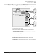


Connect external components
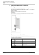
Call station interface (redundant) PTO2009
7
A6V11899867_en--_a
119 | 122
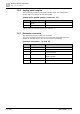
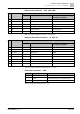
Ethernet in connectors - 'CN1' and 'CN3'
Pin
Description
Remark: when used in a 2x4 wire cable
CAT5 pin
CAT5 according to T568B
Fire alarm cables color code
according to VDE0815
1
TX+
1
White/orange
Grey
2
TX-
2
Orange
Yellow
3
RX+
3
White/green
Brown
4
RX-
6
Green
Green
5
NC
-
Do not connect
Do not connect
6
Shield
-
Shield
Shield
Table 95: PTO2009-A1 Ethernet in connectors - 'CN1' and 'CN3'
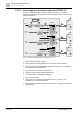
Ethernet out RJ45 connectors - 'J1' and 'J2'
Pin
Description
Remark: when used in a 2x4 wire cable
CAT5 pin
CAT5 according to T568B
Fire alarm cables color code
according to VDE0815
1
D1+/TX+
1
White/orange
Grey
2
D1-/TX-
2
Orange
Yellow
3
D2+/RX+
3
White/green
Brown
4
D3+
6
Blue
Red
5
D3-
-
White/blue
Blue
6
D2-/RX-
-
Green
Green
7
D4+
-
White/brown
White
8
D4-
-
Brown
Black
Table 96: PTO2009-A1 Ethernet out RJ45 connectors - 'J1' and 'J2'
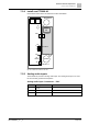
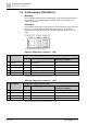
Fault relay connector - 'CN6'
Pin
Description
Remark
1
10 V
10 V reference
2
A-24 V
Closed if 'Power In A', 'CN2' has a fault
3
B-24 V
Closed if 'Power In B', 'CN4' has a fault
Table 97: PTO2009-A1 fault relay connector - 'CN6'