
Configuration Instructions


Configuration pages – Overview
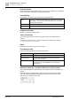
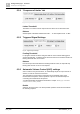
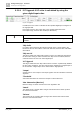
'Audio Input Configuration'
6
A6V10429097_en--_e
109 | 219
'Output'
Assignment of the set value to a local output. This output signal will be used for
calculation of the AVC algorithm.
'Threshold'
AVC takes effect if the noise level at input 4 is above this value.
'Max Attenuation' (Max Att.)
Maximum range of volume control for the AVC algorithm in dB.
'Attack'
Attack rate of the signal in dB/s. A larger value means faster sound level up if the
noise level increases.
'Release'
Release rate of the signal in dB/s. A larger value means faster volume down if the
noise level decreases.
'Averaging Time'
Defines the measurement cycle time. A larger number will make the AVC algorithm
more stable, but if the interval is too long, the system will need more time to react
to noise level changes.
'Feedback Factor'
This value is used for signal feedback of the configured output. A large feedback
factor means that most of the level of the output is subtracted from the feedback
input level. So the noise is very loud.
'Show RMS'
Input 1 and 2 level meters display measured RMS values to observe the AVC
calculation behavior.
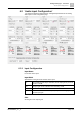
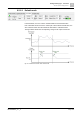
6.2.6.3 AVC-based analog measurement
Since FW1.3B5, dedicated hardware connected on I/O Expander and 1, 2 or 4
analog values can be used to generate up to 4 AVC values.
Fig. 64: AVC-based analog measurement
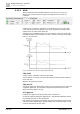
NOTICE
The connections must be made on the first 1...4 analog inputs of the first
expander.
Click the AVC level meter to view the next AVC value.