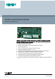
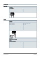
Climatix™ C400 Climatix programmable controller POL461, POL468, POL467 Climatix programmable controller C400 (POL461, POL468 and POL467) is HVAC controller optimized for residential heat pump, light commercial chiller, compact air handling unit and flat station application.
Application and features Field of application Climatix C400 are designed for residential heat pump, light commercial chiller, compact air handling unit and flat station application, to provide a broad range of control and monitoring functions. I/O mix The number and type of I/Os on the C400 are optimized for above application types.
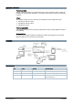
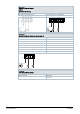
Input/output signal types Note: terminals with dotted lines vary for different variants. Please refer to below list for detailed information.
Climatix 46X variants list Hardware I/Os POL461.45/ POL468.65/ POL468.85/ STD STD STD POL467.75/ STD Analog inputs B1…B6 NTC 10 k ✓ ✓ ✓ ✓ Configurable inputs X1, X2 DC 0…10 V or 0…5 V ✓ ✓ ✓ ✓ X3, X4 NTC 10 k, DC 0…10 V ✓ ✓ ✓ ✓ X5, X6 NTC 100 k, DC: 0…10 V/0…5 V ✓ ✓ Digital inputs Configurable outputs D1, D2 Potential free (Fast DI) Active DI 24 AC/DC (Fast DI only with DC) D3, D4, D5 potential free D3, D4, D5 active AC/DC 24 V D6 potential free DL1 active AC 115….
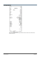
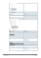
Technical data Power data Power supply DC 24 V, G0 (T7) Operating voltage DC 24 V ±10 % Max. power consumption 35 W Max. external supply line fusing 3 A slow wire fuse or circuit breaker Outputs Relay output Q1 (T10) Contact Monostable, NO/NC contact, SPDT Switching voltage (AC) AC 24…230 V (-20 %, +10 %) Switching voltage (DC) DC 5…30 V Rated current AC/DC 4 A (res.), 2 A (cosφ 0.6, ind.), Min. switching current at AC 19 V 30 mA Min.
Relay output Q2, Q3 (T11) (POL461.45/STD) Q4 (T11) Q5, Q6, Q7, Q8, Q9 (T12) Endurance 100,000 cycles at AC 230 V, 3 A (res.) Max. external supply line fusing F1 6.3 A slow wire fuse or circuit breaker Relay output Q2, Q3 (T11) (POL467.75/STD and POL468.65/STD) Contact Monostable, NO/NC contact, SPST Switching voltage (AC) AC 24…230 V (-20 %, +10 %) Switching voltage (DC) DC 5…30 V Min. switching current at AC 19 V 30mA Min. switching current at DC 5 V 100mA Rated current (ind.
Inputs Analog inputs B1…B6 (T2) NTC 10k Sensor current 120 μA at 25 °C Range 500 Ω…670 kΩ Resolution < 44 Ω at 10 kΩ Accuracy ± 221 Ω at 10 kΩ For NTC 10k (B25/85=3977 K), refer to below Temperature Accuracy Resolution -10 °C 0.8 K 0.1 K 0 °C 0.3 K 0.1 K 20 °C 0.4 K 0.1 K 50 °C 0.7 K 0.2 K 70 °C 1.3 K 0.3 K 90 °C 2.5 K 0.
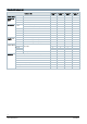
Configurable inputs and outputs Configurable inputs X3, X4 (T3) (POL461.45, POL468.65, POL467.75) Configurable By software Reference potential Terminals (M) NTC10k (B25/85=3977 K) Accuracy Refer to B1…B6 Configurable inputs X5, X6 (T3) : (POL468.85) Configurable By software Reference potential Terminals (M) NTC 100k Sensor current 96 μA at 25 °C Range 500 Ω…670 kΩ Resolution 0.04 - 0.21 k Accuracy 1.5 K full range; 0.
DC 0…5/0…10 V input Ratio-metric sensors Resolution 50 mV Accuracy 100 mV Input resistance 33 K Configurable outputs X5, X6, X7 (T4) (POL461.45/STD) X5, X6, X7, X8 (T4) (POL468.65/STD) X7, X8 (T4) (POL468.85/STD) X5, X6, X7, X8, X9 (T4) (POL467.75/STD) Configurable By software Reference potential Terminals (M) DC 0…10 V output Resolution 30 mV Accuracy 100 mV Output current Max. 1 mA PWM output Frequency 500…2.5 kHz Duty cycle 10…90 % (at an increment of 0.5 %) Max.
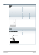
Figure 1 0/1 digital signal (binary) For voltage input Nominal voltage AC 24 V (-15 %, +10 %) DC 24 V (-10 %, +10 %) Frequency range 45…65 Hz Input current 3.4 mA @ AC 24 V 6.7 mA @ DC 24 V Delay 100 ms Pulse frequency Max. 5 Hz Figure 2 Pulse measurement Sensor Open-collector Sampling voltage DC 24 V Max.
Digital inputs D3, D4, D5 (T5) (POL461.45, POL467.75 and POL468.65) D6 (POL461.45 only) Delay 10 ms Pulse frequency Max. 20 Hz See Figure 1 on Page 10. Active digital input D3, D4, D5 (T13) (POL468.85/STD only) 0/1 digital signal (binary) For voltage input Nominal voltage AC 24 V (-15 %, +10 %) DC 24 V (-10 %, +10 %) Frequency range 45…65 Hz Input current 3.4 mA @ AC 24 V 6.7 mA @ DC 24 V Delay 100 ms Pulse frequency Max. 5 Hz See Figure 2 on Page 10.
WARNING ● ● ● ● The relay circuits have no internal fuse. An external supply line fuse is required (for fuse set of Q2 and Q3, refer to basic documentation A6V11276161). Do NOT mix SELV / PELV and mains power on the same terminal block. Use external protection for inductive load. Avoid negative voltages at the analog inputs since conversion leads to undetermined results. Maintain clearing distance of 6.4mm between SELV/PELV and mains power when different terminal blocks are used.
Interfaces On-board RS-485 (Modbus RTU) A+, B-, REF(T1) RS-485 (EIA-485) Modbus RTU or BACnet MS/TP1) mode Bus connection A+, B-, REF Bus electronics Galvanically isolated Bus cable Shielded if length > 3 m, twisted pair Bus polarization Configurable by software2) Bus termination None3) Baud rate Max. 57,600 1) BACnet MS/TP 2) Climatix POL46X controllers offer software configurable polarization at the RS485 port. Bus polarization can be enabled or disabled.
Tool USB Use PC service cable POL0C2.40/STD for tools Ethernet TCP/IP port (T-ETHERNET) POL467.75/STD and POL468.65/STD Plug RJ45 Interface type 10 base-T and 100 base-TX, IEEE802.
Download button Along with a USB stick, the download button provides a simple and fast method for loading firmware and application files to the controller without additional tools. Additional information on the download button is available in the SCOPE tool online help. Data Matrix Code and QR Code Data Matrix Code (DMC) and QR code The controller has a Data Matrix Code (DMC) and QR on the label. You can scan the code using a code reader app.
Battery Back-up battery Permissible battery type BR2032 Operating temperature -30…80 ℃ Lifetime Continuous power supply for 1 year Refer to specifications from battery manufacturer WARNING ● ● Power off before replacing batteries. Avoid accidental battery fall out to PCB. USB USB stick Max. capability 32 GB File system FAT and FAT32 Function Download BSP or application Supported current 100 mA Supported type USB 2.
Standards, directives and approvals compliance, materials composition, packaging, environmental benefit, disposal). FCC NOTICE This equipment complies with the FCC Rules CFR 47 Part 15 Emission Class B limits. This equipment has been tested and found to comply with the limits for a Class B, digital device, pursuant to Part 15 of the FCC Rules. These limits are designed to provide reasonable protection against harmful interference in a residential installation.
Accessories Product number Stock number Description POL0C2.40/STD BPZ:POL0C2.40/STD PC service cable 1.5 m POL0B5.55/STD S55843-Z555-F100 Power Supply DC 24 V / 75 W POL903.00/100 S55803-Y130-A100 WLAN stick POL002.43/STD S55843-Z124-D100 Connector for remote EXT-IO Connectors It is highly recommended that, the Climatix controllers use Phoenix connectors certificated by Siemens. The connectors are listed below and can be ordered from Siemens.
Product number Stock number Description POL005.35/STD S55843-Z133-F100 RAST5, grey, 3 pole POL004.35/STD S55843-Z143-F100 RAST3.81, green, 3 pole POL004.25/STD S55843-Z142-F100 RAST3.81, green, 2 pole POL004.55/STD S55843-Z145-F100 RAST3.81, green, 5 pole POL004.65/STD S55843-Z146-F100 RAST3.81, green, 6 pole POL004.75/STD S55843-Z147-F100 RAST3.81, green, 7 pole POL004.85/STD S55843-Z148-F100 RAST3.
POL461.45/STD POL468.xx/STD ① Five screws (GB818-M3.5×8) and ① Seven screws (GB818-M3.5×8) five washers (⌀ 4) and seven washers (⌀ 4) ② Five standoffs M3.5×L (L>10 mm) ② Seven standoffs M3.5×L (L>10 mm) POL467.75/STD ① Seven screws (GB818-M3.5×8) and seven washers (⌀ 4) ② Seven standoffs M3.5×L (L>10 mm) Note: Mounting screws and washers are not included in the delivery package. WARNING Always mount the controller with insulation washers.
Warranty Technical data on specific applications are valid only together with Siemens products listed under "Equipment combinations". Siemens rejects any and all warranties in the event that third-party products are used. Open Source Software (OSS) Software License Summary These devices incorporate open source software (OSS), please refer to the OSS document for the specific controller type and valid version set.
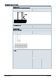
Connection terminals POL461.
POL467.
POL468.
POL468.
Dimensions Dimensions in mm POL461.45/STD POL468.xx/STD POL467.
Siemens Smart Infrastructure 27 A6V11276159_en--_c 2020-09-25
Issued by Siemens Switzerland Ltd Building Technologies Division International Headquarters Theilerstrasse 1a CH-6300 Zug Tel. +41 58 724 2424 www.siemens.com/buildingtechnologies 28 Siemens Smart Infrastructure Document ID A6V11276159_en--_c Edition 2020-08-31 © Siemens Switzerland Ltd, 2020 Technical specifications and availability subject to change without notice.