
User Manual

6
Siemens
A6V11521024_en--_c
Smart Infrastructure
2020-10-15
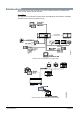
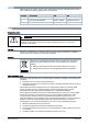
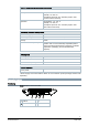
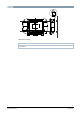
Connection terminals
USB-B
Figure
Pin
Description
1
NC
2
Data -
3
Data +
4
Ground
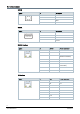
USB-A
Figure
Pin
Description
1
DC +5 V out, max. 500 mA
2
Data -
3
Data +
4
Ground
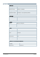
RS485 Interface
Figure
Pin
RS485
Pin on controller
1
NC
2
NC
3
RS485 A+
RS485 A+ (for
RS485 connection)
4
0 V
5
0 V
6
RS485 B-
RS485 B- (for RS485
connection)
7
24 V
8
24 V
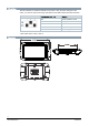
IP interface
Figure
Pin
LAN
Pin on controller
1
TX+
TX+
2
TX-
TX-
3
RX+
RX+
4
0 V
5
0 V
6
RX-
RX-
7
24 V
8
24 V