POS8.4420/109; POS8.
Table of Contents 1 About this document ....................................................................................3 1.1 Revision history ...............................................................................................3 1.2 Before you start ...............................................................................................3 1.3 Reference documents .....................................................................................4 2 Product overview ...........
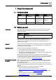
About this document 1 Revision history 1 About this document 1.1 Revision history Revision Date Changes Section c October 2020 Canceled POS3.3515/100 Chapter 2.1.1 b August, 2019 Added chapter “Engineering” and “Object list” Chapter 5 and Chapter 10 a November, 2018 First edition All 1.2 Before you start Trademarks The table below lists the third-party trademarks used in this document and their legal owners.
1 About this document Reference documents Siemens assumes no liability to the extent allowed under the law for any losses resulting from a failure to comply with the aforementioned points or for the improper compliance of the same. 1.3 Reference documents 4 | 73 Ref.
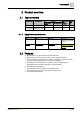
Product overview 2 Type summary 2 Product overview 2.1 Type summary Product number 2.1.1 Stock number Feature LCD display Minimal with order backlight size Temperature sensor Humidity sensor POS8.4420/109 S55625-H422-A100 Yes No Yes 20 POS8.4440/109 S55625-H444-A100 Yes Yes Yes 20 Equipment combinations Type Type no. Document ID Description Controller POS3.5715/100 A6V11417931 For HVAC control, switching and monitoring functions Controller POS3.
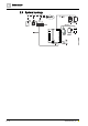
2 Product overview System topology 2.
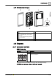
Product overview Mechanical design 2 2.4 Mechanical design 1 Gasket for panel mounting 4 KNX PL-Link bus connector 2 Base plate with 5 Jack connector for tool connection 3 ● screw holes for all common conduit boxes ● guide channels for wiring from center, up, or bottom Room operator unit 2.5 Diagrams 2.5.
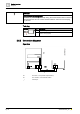
2 Product overview Diagrams NOTICE Wires are NOT interchangeable! The device is protected against faulty wiring, but communication does not work on interchanged wires. Do not connect the KNX / KNX PL-Link bus to the tool plug, only the tool. Tool plug Connector 2.5.2 Pin Description + KNX PL-Link (positive) - KNX PL-Link (negative) Connection diagrams Operation R1 The device - room operator unit (POS8.
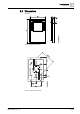
Product overview Dimensions 2 2.
3 Important information on safety and disposal General regulations 3 Important information on safety and disposal This section explains general and system-specific regulations for mains and operating voltages. It includes important information for your safety and the safety of the entire plant. 3.1 General regulations Comply with the following general regulations during engineering and execution: ● Electrical and mains power regulations for the given country. ● Other applicable, national regulations.
Important information on safety and disposal Disposal 3 3.4 Disposal The device is considered an electronic device for disposal in accordance with the European Guidelines and may not be disposed of as domestic garbage. ● Dispose of the device through channels provided for this purpose. ● Comply with all local and currently applicable laws and regulations.
4 Mounting and installation Preparation 4 Mounting and installation Comply with the following notes as well as the Mounting instructions (A6V10733764) to mount the room operation unit. 4.1 Preparation Check package contents Check the package contents for visible signs of transport damage and for completeness. Do not install parts damaged during shipment. Contact your Siemens representative in the event of damaged parts.
Mounting and installation Mounting instructions 4 4.2 Mounting instructions Mounting instructions ● Mounting instructions A6V10733764 are enclosed with the devices. ● Remove the breakout on the housing before putting the cable into the gaining channel. If 4-wire cables are used for daisy chain wiring, remove the cable coating, as it will not fit in the gaining channel.
4 Mounting and installation Mounting instructions Dismounting/service 14 | 73 A6V11471220_en--_c
Engineering 5 5 Engineering TempOutsideEff UHD (User HVAC Display) Process Data IR.
5 Engineering UHD (User HVAC Display) Process Data IR.ind TempRoomEff Management Data ObjectType 390 Configuration Data BuildingZone Room Subzone Value (U8Z8) Value (U8Z8) Value (U8Z8) HumRelRoomEff UHD (User HVAC Display) Process Data IR.
Engineering 5 Property name Property identifier Property access LTE service Description KNX Datapoint Type (DPT) Interface Object Type 1 R --- 390 = UHD DPT_PropData Type (DPT_ID = 7.010) TempOutsideEf OTS.155 f ---- IR.ind Process Data Input DPT_TempHV ACAbs_Z local copy *) 155 R --- Diagnostic Value TempRoomEff RTS.155 ---- IR.ind Process Data Input local copy *) 157 R --- Diagnostic Value HumRelRoomE RRHS.155 ff ---- IR.
5 Engineering Property name Property identifier Property access LTE service Description KNX Datapoint Type (DPT) Interface Object Type 1 R --- 384 = UHRS DPT_PropData Type (DPT_ID = 7.010) HVACModeUs er 55 R IR.req Process Data Output DPT_HVACMo de_Z HVACModeUs erLocked 156 R/W W.ind Process Data Input DPT_Bool HVACModeUs erEff RSMHD.57 ---- IR.
Engineering 5 Building Automation Device BA-Model BA-Binary-Calculated-Value 1 Present-Value 1 Tracking-Value No-fault Reliability false Out-of-Service Status-Flags: false Overridden false Out-of-Service false Fault In-Alarm false unoccupied Inactive-Text Active-Text occupied I/O-Address Present-Value Present-Priority Why-Indication[16] Relinquish-Default Reliability Out-of-Service Status-Flags: Overridden Out-of-Service Fault In-Alarm Inactive-Text Active-Text I/O-Address PL-1:PR=UPS.
Engineering 5 Temporary mode Building Automation Device Room Control Room 1 BA-Model Binary-Calc-Value ResetTmpFanRequest Analog-Proc-Value TemporaryFanRemainTime Analog-Calc-Value ManualFanSpeed Binary-Calc-Value KitchenHoodRequest Present-Value Binary-Calc-Value ManualFanMode 15 min Multistate-Proc-Value TemporaryFanMode Present-Value FirePlaceMode Binary-Calc-Value FirePlaceRequest Binary-Calc-Value FanBoostRequest Present-Value Update-Count Active n PL-1:PR=FSSM.
Engineering 5 Property name Property identifier Property access LTE service Description KNX Datapoint Type (DPT) Interface Object Type 1 R --- 390 = UHD DPT_PropData Type (DPT_ID = 7.010) TmpFanMode FSSM.166 ---- IR.ind Process Data Input DPT_TmpFan Mode local copy *) 208 R --- Diagnostic Value TmpFanModeR FSSM.167 emainTime ---- IR.
5 Engineering SARB HVAC Room Unit User HVAC RoomSettings UHRS User HVAC Display UHD RoomGroup 24.6.1 LTE IR (+1K) LTE W (false) TempRoomSetpUserOffsetEff RoomGroup 24.6.1 TempRoomSetpUserOffset LTE IR (+1K) LTE W (-3K) TempRoomSetpUserOffsetMin LTE W (+3K) TempRoomSetpUserOffsetMax LTE IR (15) Device Configuration Data TxtCatalog Management Data UHRS Configuration Data 24.6.1 …..
Engineering Property access LTE service Description KNX Datapoint Type (DPT) StepIncrement 171 HMI_TRSetpUs Offset R/W --- Configuration Data DPT_Value_1_ Ucount BuildingZone 101 R/W --- Configuration Data DPT_UCountV alue8_Z Room 102 R/W --- Configuration Data DPT_UCountV alue8_Z Subzone 103 R/W --- Configuration Data DPT_UCountV alue8_Z Property name Property identifier 5 Temperature Temporary mode(Comfort prolongation) SARB HVAC Room Unit User HVAC RoomSettings UHRS User
5 Engineering Property name Property identifier Property access LTE service Description KNX Datapoint Type (DPT) Interface Object Type 1 R --- 390 = UHD DPT_PropData Type (DPT_ID = 7.010) ComfortProlon gEff RSMHD.60 *) ---- IR.
Engineering Building Automation Device 5 Control Program BA-Model Binary Calculated Value Multistate-Calculated-Value Present-Value Present-Value Number-of-States Active Multistate-Process-Value Auto 5 Auto Normal Reduced Off/FrostProtect LegioProtect State-Text Present-Value Priority-Array Present-Priority Number-of-States Why-Indication [16] State-Text Update-Count n Update-Count PL-1:PR=DHWSM. DHWPushUser; APP=DHW.1; I/O-Address n PL-1:PR=DHWSM. DHWModeUser; APP=DHW.
5 Engineering Property name Property identifier Property access LTE service Description KNX Datapoint Type (DPT) Interface Object Type 1 R --- 181 = UDHWSET DPT_PropData Type (DPT_ID = 7.010) DHWModeUse r 51 R IR.req Process Data Output DPT_DHWMod e_Z DHWModeUse rLocked 156 R/W W.ind Process Data Input DPT_Bool DHWModeUse rEff DHWSM.56 ---- IR.
Engineering 5 Building Automation Device Control Program BA-Model Analog-Calculated-Value Analog-Process-Value Present-Value Units 58°C °C Min-Present-Value Max-Present-Value 45°C 60°C Update-Count n PL-1:PR=DHWSM. TempDHWSetpEff; APP=DHW.1; I/O-Address 58°C …. 15 °C x Update-Count n n PL-1:PR=DHWSM. TempDHWSetpUserEff; APP=DHW.1; I/O-Address represent represent represent PL-Link Data Acquisition Present-Value Priority-Array Present-Priority Units Why-Indication [16] 65°C ….
5 Engineering Property name Property identifier Property access LTE service Description KNX Datapoint Type (DPT) Interface Object Type 1 R --- 181 = UDHWSET DPT_PropData Type (DPT_ID = 7.010) TempDHWSet pUser 52 R IR.req Process Data Output DPT_TempHV ACAbs_Z TempDHWSet pUserEff DHWSM.162 ---- IR.ind Process Data Input DPT_TempHV ACAbs_Z local copy *) 246 R --- Diagnostic Value TempDHWSet pUserMinIN 158 R/W W.
Engineering 5 Building Automation Device Control Program BA-Model Analog-Process-Value Present-Value Units 53°C °C PL-1:PR=DHWTS. TempDHWEff; APP=DHW.
5 Engineering Property name Property identifier Property access LTE service Description KNX Datapoint Type (DPT) Interface Object Type 1 R --- 181 = UDHWSET DPT_PropData Type (DPT_ID = 7.010) DHWPushActiv DHWSM.163 e ---- IR.
Engineering 5 Building Automation Device Engineering & Commissioning Control Program Operation & Monitoring configure & commission automate & control operate & monitor Building Automation Model BA-Peripheral-Device-Object BA-Schedule-Object OpMSched operational “RU_B“ Present-Value Peripheral-Dev-Type Weekly-Schedule Mo … … … … ... PDO-Config-“RU_B“ true ... IO-Extension Enable-Weekly-Sched-Op ... Tu … … … … ... We … … … … ... Th … … … … ... Fr … … … … ... Sa … … … … ... Su … … … … ...
5 Engineering Property name Property identifier Property access LTE service Description KNX Datapoint Type (DPT) HVACSDailyPr og_Th 1) 234 R/W --- Daily Program Thursday DPT_HVACSS witchPoint HVACSDailyPr og_Fr 1) 235 R/W --- Daily Program Friday DPT_HVACSS witchPoint HVACSDailyPr og_Sa 1) 236 R/W --- Daily Program Saturday DPT_HVACSS witchPoint HVACSDailyPr og_Su 1) 237 R/W --- Daily Program Sunday DPT_HVACSS witchPoint Adjust clock 32 | 73 A6V11471220_en--_c
Engineering Building Automation Device 5 Control Program BA-Model Device-Object Local-Time Local-Date UTC-Offset Daylight-Savings-Status 10:36:28 31-05-2010; Monday 120 true Firmware (OS) PL-Link Data Acquisition System Clock SCLO (Master) LTE Broadcast SystemClock LTE IR (2010-05-31;Mon;10:36:28;SuTi) RelToGMT LTE IR (120min) SCLO Configuration Data Peripheral Zone SCLOMode SystemClockHeartbeat EnableSystemClockSetting PL-Link Room Unit Optional feature; no real use case on PL-Link so far => n
Engineering 5 Notification: Alarm / Service Building Automation Device Control Program ‚Alarm’ Detection Detection Control Program ‚Maintenance’ Aggregate & Select State Machine Aggregate & Select Detection Detection State Machine BA-Model MPV-Object ErrorIndicationRU APV-Object ErrorCodeRU MPV-Object ErrorCmd-StateRU PL-Link Data Acquisition MPV-Object MaintenanceIndicationRU MTV-Object ErrorCmd-RU APV-Object MaintenanceCodeRU MPV-Object MaintenanceCmd-StateRU MTV-Object MaintenanceCmd-RU
Engineering 5 Property name Property identifier Property access LTE service Description local copy 2) 229 R --- Diagnostic Value MaintenanceInf ALSRC.194 o_CS --- IR.ind Process Data Input local copy 1) R --- Diagnostic Value --- W.req Process Data Output DPT_Ack Property identifier Property access LTE service Description KNX Datapoint Type (DPT) local copy 2) 225 R --- Diagnostic Value ALSRC.193 --- W.
Engineering 5 Building Automation Device Control Program BA-Model Multistate-Process-Value Present-Value Priority-Array Present-Priority Why-Indication[16] Number-of-States Multistate-Input-Object Present-Value EconomySwitch Manual override of HVACMode via a hardware contact will normally result in Present-Priority=7 State-Text Update-Count Economy …. 7 x 4 Protection Economy Precomfort Comfort n PL-1:PR=RSMHD. HVACModeEff; GEO=24.6.
Engineering A6V11471220_en--_c 5 Property name Property identifier Property access LTE service Description KNX Datapoint Type (DPT) BuildingZone 101 R/W --- Configuration Data DPT_UCountV alue8_Z Room 102 R/W --- Configuration Data DPT_UCountV alue8_Z Subzone 103 R/W --- Configuration Data DPT_UCountV alue8_Z 37 | 73
6 Commissioning Programming pin and service LED 6 Commissioning Prerequisites Before commissioning a room operator unit, make sure an application is downloaded onto the connected controller, from where the functions are downloaded into the room operator unit. After successful commissioning, the room operator unit displays the default operating page defined in the application loaded in the controller. Automatic commissioning (1:1 connection) In a 1:1 connection, i.e.
Commissioning Programming pin and service LED 6.1.2 6 Connection test 1. Press the programming pin (>5 s and <20 s) to test the KNX PL-Link connection. After releasing the programming pin, testing of the KNX PL-Link connection starts; the service LED flashes (1/4 s on, 7/4 s off). After approximately 12 s, the test result is displayed: - If the test is positive, the LED is lit continuously. - If the test fails, the LED flashes (1 s on, 1 s off). 2.
7 Technical data 7 Technical data Power supply Operating voltage KNX PL-Link DC 21...30 V Max power consumption 7...10 mA Interfaces Type of port between controller and room operator unit KNX PL-Link Baud rate 9.6 kbps Protocol KNX PL-LINK Standard KNX connector Wire diameter 0.8 mm, max. 1.0 mm (solid conductors only) Cable type 2-core twisted pair, stranded, solid Single cable length (from room automation station to room operator unit) <1000 m Section 0.5…1.
Technical data 7 Standards, directives and approvals EU conformity (CE) A6V11210253 *) RCM conformity to EMC emission standard A6V11210257 *) IC compliance CAN ICE-3(B)/NMB-3(B) UL compliance UL916 FCC compliance Part 15 of the FCC rules. Operation is subject to the following two conditions: 1) this device may not cause harmful interference, and 2) this device must accept any interference received, including interference that may cause undesired operation.
8 Functions 8 Functions Elements / Functions Operating modes: Home / Away / Temporary / Temporary modes: Ventilation boost / Fireplace / / / / / HVAC modes: Comfort / Economy / Unoccupied / Protection Auto / Manual Manual Ventilation Temperature Domestic hot water Notification Clock / / General / Expert Indicates an operable element Wait Start List Alarm (A-alarm) notification abnormal and unacknowledged Alarm(A-alarm) notification normal and unacknowledged Alarm (A-alarm) notification abnormal
Functions Elements 8 Functions Confirm Cancel Go back / +/- Exit / next Increase / decrease Add a switching point Edit Delete 1234567 1=Monday, 2=Tuesday, …, 6=Saturday, 7=Sunday Time Switch point Scheduler bar Read parameter Outside temperature Room temperature Auxiliary input for Comfort Auxiliary input for Economy Auxiliary input for Unoccupied Auxiliary input for Protection Auxiliary input for Ventilation Auxiliary input for fireplace Auxiliary input for kitchen hood A6V11471220_en--_c 43 | 73
9 Operation Ventilation page 9 Operation 9.
Operation Temperature page 9 In away mode Buttons 1 and 5 Toggle through home mode, temporary mode and away mode Buttons 2, 3, 4, 6, 7 and 8 No function (no arrow symbols displayed) 9.
9 Operation Domestic hot water page Buttons 1 and 5 Toggle through home mode, temporary mode and away mode Buttons 2, 3 and 6 No function (no arrow symbol displayed) Buttons 7 Press to start the selected temporary mode: Ventilation boost or fire place Buttons 4 and 8 Toggle through different pages: Ventilation, temperature, domestic hot water, notification, and clock. 9.
Operation Notification page 9 9.4 Notification page Press button 4 or 8 from the default page to enter the notification page. With no pending notification, the following is displayed: Alarm notification When an event comes in, e.g., event number 1236, the following is displayed: Press any button to enter the next page: Note: stands for type 1: Alarm notification. When a new alarm comes in, it overrides the existing one. The screen continues to show type 1.
9 Operation Notification page Then press button 5 to send a request to the controller to acknowledge all alarms. The following is displayed while waiting for the feedback from the controller. The following is displayed automatically after all alarms are acknowledged. With only notifications left, press button 7 to enter the reset page. On the reset page, press 3 or 7 to switch between notification and reset page.
Operation 9 Notification page The notifications are deleted after resetting and the screen returns to the notification page. Service notification For events , , , , or , there is no pop up screen. To check the notifications, press button 4 or 8 on the default page to enter the notification page as below: Note: stands for type 2: Service notification. A new service notification overrides the existing one. The screen continues to show type 2.
9 Operation Notification page Press button 5 to send a request to the controller to acknowledge all notifications. The following page is displayed while waiting for the feedback from the controller. The following is displayed automatically after all notifications are acknowledged. Service notifications disappear and the screen returns to the notification page after the device receives a maintenance, normal and Acked (acknowledged) feedback from the controller.
Operation 9 Clock page 9.5 Clock page Buttons 1, 2, 3, 6, and 7 No function (no arrow symbols displayed) Button 5 Press to edit the time and date Buttons 4 and 8 Toggle through different pages: Ventilation, temperature, domestic hot water, notification and clock 9.
9 Operation Standard and expert settings Button 1 Press to exit and save the settings Buttons 2, 4 and 6 No function (no arrow symbol displayed) Buttons 3 and 7 Toggle through switch points Button 5 Press to add a switch point Button 8 Press to edit the switch point A maximum of 15 switching points can be added. 9.
Operation Standby page Button 1 Press to exit and save the settings Buttons 2 and 6 Press to select a setting Buttons 3 and 7 Toggle through the parameters Buttons 4, 5 and 8 No function (no arrow symbols displayed) 9 For detailed information about the parameters, refer to Parameters [➙ 54]. 9.8 Standby page When no operation occurs on the screen for a while, the room operator units turns off backlighting and displays the standby page automatically. There are 5 types of standby pages.
Appendix 10 Parameters 10 Appendix 10.1 Parameters Parameters for standard settings Parameters Description Default P01 Backlighting level: 1, 2, …, 10 5 P02 Standby page types: 1, 2, …, 5 1 1: room temperature 2: room temperature and time 3: room temperature, time and outside air temperature 4: room temperature, time, outside air temperature and customer logo 5: room temperature, time, outside air temperature and relative humidity P03 Room operator unit temperature correction: -3.0…3.0 K 0.
Appendix Object list A6V11471220_en--_c 10 PID_DEVICE 14 _CONTROL 1 B8 / RW ---PDT_BITSET8 [DPT_Device_C ontrol (DPT_ID = 21.002)] VerifyMode Contol for UserMemery_Write Service is done via this property. Bit2 is the Verify-Mode Flag. When using connectionless UserMemWrite, then verifyMode shall be active KNX Standard: chapter 3-5-1, clause 4.2.14 PID_DEVICE_CONTR OL chapter 3-5-2, clause 3.19 DM_UserMem_Write PID_ORDER 15 _INFO 1 PDT_GENERIC R _10 DPT_OrderInfo (DPT-ID = 60110.
Appendix 10 3 Object list 1 50100 1 56 | 73 7 9 DevIdentHop 24 CountType 3 1 N8 / RW ---PDT_ENUM8 DPT_HopCount Type Defines the used hop count for DevIdent: 0: PSD defined 1: 0 7: 7 All others: reserved DevIdentTrig ger 24 4 1 B1 / RW W.in PDT_BINARY_I d NFORMATION B1 / DPT_Trigger Triggers sending of DevIdent when DevIdentAutoSend is false.
Appendix Object list 10 3 1 U8Z8 / RW ---DPT_UcountVal ue8_Z ACS Product 51 ID 1 PT_GENERIC_ 12 DPT_AcsProdu ctId (DPT-ID = 60112.60000) R ---- PlantImageId 53 entification 1 DPT_GENERIC R _10 ---- Device Ident 90 1 DPT_GENERIC R _10 ---- VersionArray 91 1 U5U5U6 / DPT_Version R FW_Upgrade 12 _Checksum 1 16 FW_Upgrade 12 _Length 2 AutoSyncAd dress Subzone 10 Contains serial no., device family etc. is constant for a given device.
10 58 | 73 Appendix Object list ObjectIndex 29 1 U8 / R PDT_UNSIGNE D_CHAR U8 / DPT_Value_1_ Ucount Apartment 10 1 1 U8Z8 / RW ---DPT_UcountVal ue8_Z Room 10 2 1 U8Z8 / RW ---DPT_UcountVal ue8_Z Subzone 10 3 1 U8Z8 / RW ---DPT_UcountVal ue8_Z UI_Tstd 11 1 1 U8 / DPT_Value_1_ Ucount RW ---- Delay Time since last operation in [sec] This time is fixed for 4min10sec . The default display will be loaded if no operations on the RU in the period of UI_Tstd.
Appendix Object list 321 1 13 RTS Room Temper ature Sensor A6V11471220_en--_c Bootloader_V 12 ersion 4 1 U5U5U6 / DPT_Version R EnableSched 20 ulerOperatio 1 n 1 DPT_Enable RW ---- [T022.S0552D040.001] PropertyList of ABI CPC“RU_B” EnableSyste 20 mClockSettin 2 g 1 DPT_Enable RW ---- [T022.S0552D040.
Appendix 10 390 60 | 73 Object list 1 14 UHD User HVAC Display TempRoom MinRepTime 11 6 1 U16 / RW ---DPT_TimePerio dSec Minimum repetition time for sending of the room temperature process value output. Interface Object type 1 1 U16 / R PDT_UNSIGNE D_INT ---- ObjectIndex 29 1 U8 / R PDT_UNSIGNE D_CHAR U8 / DPT_Value_1_ Ucount Rea needed for Object d.ind Index Discovery via LTE-Read onto this Property TempOutside 15 Eff 5 1 V16Z8 / R DPT_TempHVA CAbs_Z IR.
Appendix Object list A6V11471220_en--_c 10 TmpFanMod e 20 8 1 N8 / PDT_ENUM8 R IR.in TmpFanMode refers to d the optional process input property of AB UHD to indicate on the Room Unit (e.g. RU-B) if a temporary HRV fan mode is active Enumeration value - 0: None - 1: FanBoostMode - 2: FirePlaceMode - 3: KitchenHoodMode TmpFanMod eRemainTim e 20 9 1 U16 / R DPT_TimePerio dSec IR.
Appendix 10 1001 62 | 73 Object list 1 15 SCLO System Clock DelayedHVA CModeEff 17 1 1 N8 R IR.in DelayedHVACModeEff d refers to the proprietary and optional process input property to indicate if a manually triggered room operating mode is delayed by an application specific function (e.g. unoccupied selection and delayed HOME (Comfort) -> AWAY (Economy) transition). DelayedHVACModeEff is provided by ABI RSMHD TmpFanMod eCountdown 21 6 1 DPT_State R IR.
Appendix Object list ObjectIndex 29 1 R SystemClock 51 1 U8[r4U4][r3U5][ R U3U5][r2U6][r2 U6]B16 / DPT_DateTime DPT_ID = 19.001 10 ---IR.in Received d SystemClock information from Automation Device which is always master SCLO; updated every 10 minutes Time, date and weekday are required to display: Fri, 9, 14:24 6E 01 01 00 00 00 00 00 --> 10.1.
Appendix 10 391 Object list 1 16 UPS Interface User Object type Presenc e Switch 1 1 U16 / R PDT_UNSIGNE D_INT 29 1 R Rea d.ind PresenceStat 51 us 1 DPT_Occupanc R y IR.
Appendix Object list KitchenHood Req 384 1 18 16 4 1 B1 / R PDT_BINARY_I NFORMATION IR.re KitchenHoodReq q refers to the optional process output property of AB UFS representing a trigger command requested by the room occupant to initiate the temporary Kitchen Hood fan mode in HRV applications. => cASA-[T022.S0352I055] Fan operation: Fan Boost/Fire Place/Kitchen Hood ResetTmpFa 16 nReq 5 1 B1 / R PDT_BINARY_I NFORMATION IR.
Appendix 10 Object list U 66 | 73 ComfortProlo 53 ngUser 1 B1 / DPT_Trigger R IR.re Trigger to start an q additional period of Comfort Mode 1 = Trigger (0 not used) HVACModeU 55 ser 1 N8Z8 / DPT_HVACMo de_Z R IR.re HVACMode user q request: 0 = AUTO 1 = Comfort 2 = Standby (PreComfort) 3 = Economy 4 = Building.Prot. HVACModeU 15 serLocked 6 1 B1 / DPT_Bool RW W.in d HVACModeU 15 serEff 7 1 N8Z8 / DPT_HVACMo de_Z R TempRoomS 15 etpUserOffse 8 tMinIN 1 V16Z8 / RW W.
Appendix Object list 1003 1 19 ALSNK - Alarm Sink A6V11471220_en--_c 10 TempRoomS 11 etpUserOffse 3 tMin 1 V16Z8 / RW ---DPT_TempHVA CRel_Z Config value for Max. => cASA-[T022.S031negative Offset of 2]-SARB-DataTempRoomSetpUserO Mapping-HVAC ffset TempRoomS 11 etpUserOffse 4 tMax 1 V16Z8 / RW ---DPT_TempHVA CRel_Z Config value for Max. => cASA-[T022.
Appendix 10 Object list 22 9 1 PDT_BINARY_I R NFORMATION / DPT_Reset W.re AlarmReset refers to q the process output property of AB ALSNK to trigger the reset of the locked state of the BA-Device (caused by an Alarm indication) via PL-Link Room Units like RU-B. AB ALSNK acts as a property client to write input AlarmReset of the remote ABI ALSRC Maintenance 22 Acknowledge 5 1 PDT_BINARY_I R NFORMATION / DPT_Ack W.
Appendix Object list 181 1 22 HVACSDaily Prog_We 23 3 15 DPT_HVACSS witchPoint R ---- Daily Program Wednesday HVACSDaily Prog_Th 23 4 15 DPT_HVACSS witchPoint R ---- Daily Program Thursday HVACSDaily Prog_Fr 23 5 15 DPT_HVACSS witchPoint R ---- Daily Program Friday HVACSDaily Prog_Sa 23 6 15 DPT_HVACSS witchPoint R ---- Daily Program Saturday HVACSDaily Prog_Su 23 7 15 DPT_HVACSS witchPoint R ---- Daily Program Sunday 1 1 U16 / R PDT_UNSIGNE D_INT ---- User DHW Set
10 70 | 73 Appendix Object list DHWModeU ser 51 1 N8Z8 / DPT_DHWMod e_Z R IR.re DHWModeUser refers q to the process output property of AB UDHWSET to change the DHW user operating mode via a Room Unit. • Supported Z8-States: OutOfService • Default Value (after powerup) = OutOfService • DHWModeUser must not be sent after a reboot of the Room Unit. Transmission of DHWModeUser may be triggered by user interaction on the HMI only. • Heartbeat: no DHWModeU serLocked 15 6 1 B1 / DPT_Bool RW W.
Appendix Object list A6V11471220_en--_c 10 DHWPushAc 25 tive 2 1 B1 / DPT_Bool TempDHWS etpUserEff 24 6 1 V16Z8 / R DPT_TempHVA CAbs_Z IR.in TempDHWSetpUserEf => [T022.S040d f refers to the process 3D015.010] input property of AB TempDHWSetpUser UDHWSET to indicate => [T022.S040the effective user 3D015.360] defined DHW TempDHWSetpUserMi temperature setpoint n for ‘Normal’ mode • DWW temperature setpoint editing shall start with the current value of property TempDHWSetpUserEf f.
10 72 | 73 Appendix Object list TempDHWS etpUserLock ed 16 0 1 B1 / DPT_Bool TempDHWS etpUserMin 16 1 1 TempDHWS etpUserMax 16 2 DHWZone_C 10 ontroller 1 R/ W W.in d TempDHWSetpUserL ocked refers to the proprietary input process signal of AB UDHWSET to lock or enable the manual adjustment of TempDHWSetpUser on the Room Unit.
Issued by Siemens Switzerland Ltd Smart Infrastructure Global Headquarters Theilerstrasse 1a CH-6300 Zug +41 58 724 2424 www.siemens.com/buildingtechnologies A6V11471220_en--_c © Siemens Switzerland Ltd, 2019 Technical specifications and availability subject to change without notice.