POS8.4420/109; POS8.
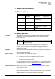
Table of Contents 1 About this document ....................................................................................3 1.1 Revision history ...............................................................................................3 1.2 Before you start ...............................................................................................3 1.3 Reference documents .....................................................................................4 2 Product overview ...........
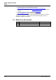
1 About this document Revision history 1 About this document 1.1 Revision history Revision Date Changes Section e Sep 2021 Added info for blinking screen Chapter 5 and Chapter 9 d May 2021 Added info for POS8.4440/109 about humidity Chapter 7 c October 2020 Canceled POS3.3515/100 Chapter 2.1.1 b August, 2019 Added chapter “Engineering” and “Object list” Chapter 5 and Chapter 10 a November, 2018 First edition All 1.
1 About this document Reference documents ● On the intranet (for Siemens employees only) at https://workspace.sbt.siemens.com/content/00001123/default.aspx ● At your next Siemens branch office www.siemens.com/sbt or at your system suppliers. ● From the support team in the headquarters fieldsupportzug.ch.sbt@siemens.com if no local contact is available.
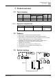
2 Product overview Type summary 2 Product overview 2.1 Type summary Product number Stock number Feature LCD display with backlight Minimal order size Temperature sensor Humidity sensor POS8.4420/109 S55625-H422-A100 Yes No Yes 20 POS8.4440/109 S55625-H444-A100 Yes Yes Yes 20 2.1.1 Equipment combinations Type Type no. Document ID Description Controller POS3.5715/100 A6V11417931 For HVAC controlling, switching and monitoring functions 2.
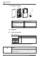
2 Product overview Mechanical design 2.4 Mechanical design 1 Gasket for panel mounting 4 KNX PL-Link bus connector 2 Base plate with 5 Jack connector for tool connection 3 ● screw holes for all common conduit boxes ● guide channels for wiring from center, up, or bottom Room operator unit 2.5 Diagrams 2.5.
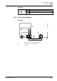
Product overview Diagrams 2 Tool plug Connector Pin Description + KNX PL-Link (positive) - KNX PL-Link (negative) 2.5.2 Connection diagrams Operation R1 The device - room operating unit (POS8.
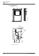
2 Product overview Dimensions 2.6 Dimensions Unit: mm Fig. 1: Dimensions for housing Fig.
3 Important information on safety and disposal General regulations 3 Important information on safety and disposal This section explains general and system-specific regulations for mains and operating voltages. It includes important information for your safety and the safety of the entire plant. 3.1 General regulations Comply with the following general regulations during engineering and execution: ● Electrical and mains power regulations for the given country. ● Other applicable, national regulations.
3 Important information on safety and disposal Disposal 3.4 Disposal The device is considered an electronic device for disposal in accordance with European Directive and may not be disposed of as domestic waste. ● Use only designated channels for disposing the devices. ● Comply with all local and currently applicable laws and regulations.
Mounting and installation Preparation 4 4 Mounting and installation Comply with the following notes as well as the Mounting instructions (A6V10733764) to mount the room operation unit. 4.1 Preparation Check package contents Check the package contents for visible signs of transport damage and for completeness. Do not install parts damaged during shipment. Contact your Siemens representative in the event of damaged parts.
4 Mounting and installation Mounting instructions 4.2 Mounting instructions Mounting instructions ● Mounting instructions A6V10733764 are enclosed with the devices. ● Remove the breakout on the housing before putting the cable into the gaining channel. If 4-wire cables are used for daisy chain wiring, remove the cable coating, as it will not fit in the gaining channel.
Mounting and installation Mounting instructions 4 Dismounting/service A6V11471220_en--_e 13 | 70
5 Engineering 5 Engineering TempOutsideEff UHD (User HVAC Display) Process Data IR.
Engineering 5 UHD (User HVAC Display) Process Data IR.ind TempRoomEff Management Data ObjectType 390 Configuration Data BuildingZone Room Subzone Value (U8Z8) Value (U8Z8) Value (U8Z8) HumRelRoomEff UHD (User HVAC Display) Process Data IR.
5 Engineering Property name Property identifier Property access LTE service Description KNX Datapoint Type (DPT) Interface Object Type 1 R --- 390 = UHD DPT_PropData Type (DPT_ID = 7.010) TempOutsideEf OTS.155 f ---- IR.ind Process Data Input DPT_TempHV ACAbs_Z local copy *) 155 R --- Diagnostic Value TempRoomEff RTS.155 ---- IR.ind Process Data Input local copy *) 157 R --- Diagnostic Value HumRelRoomE RRHS.155 ff ---- IR.
5 Engineering Property name Property identifier Property access LTE service Description KNX Datapoint Type (DPT) Interface Object Type 1 R --- 384 = UHRS DPT_PropData Type (DPT_ID = 7.010) HVACModeUs er 55 R IR.req Process Data Output DPT_HVACMo de_Z HVACModeUs erLocked 156 R/W W.ind Process Data Input DPT_Bool HVACModeUs erEff RSMHD.57 ---- IR.
5 Engineering Building Automation Device BA-Model BA-Binary-Calculated-Value 1 Present-Value 1 Tracking-Value No-fault Reliability false Out-of-Service Status-Flags: false Overridden false Out-of-Service false Fault In-Alarm false unoccupied Inactive-Text Active-Text occupied I/O-Address Present-Value Present-Priority Why-Indication[16] Relinquish-Default Reliability Out-of-Service Status-Flags: Overridden Out-of-Service Fault In-Alarm Inactive-Text Active-Text I/O-Address PL-1:PR=UPS.
5 Engineering Temporary mode Building Automation Device Room Control Room 1 BA-Model Binary-Calc-Value ResetTmpFanRequest Analog-Proc-Value TemporaryFanRemainTime Analog-Calc-Value ManualFanSpeed Binary-Calc-Value KitchenHoodRequest Present-Value Binary-Calc-Value ManualFanMode 15 min Multistate-Proc-Value TemporaryFanMode Present-Value FirePlaceMode Binary-Calc-Value FirePlaceRequest Binary-Calc-Value FanBoostRequest Present-Value Update-Count PL-1:PR=FSSM. TmpFanMode RemainTime; GEO=24.6.
5 Engineering Property name Property identifier Property access LTE service Description KNX Datapoint Type (DPT) Interface Object Type 1 R --- 390 = UHD DPT_PropData Type (DPT_ID = 7.010) TmpFanMode FSSM.166 ---- IR.ind Process Data Input DPT_TmpFan Mode local copy *) 208 R --- Diagnostic Value TmpFanModeR FSSM.167 emainTime ---- IR.
5 Engineering SARB HVAC Room Unit User HVAC RoomSettings UHRS User HVAC Display UHD RoomGroup 24.6.1 LTE IR (+1K) LTE W (false) TempRoomSetpUserOffsetEff RoomGroup 24.6.1 TempRoomSetpUserOffset LTE IR (+1K) LTE IR (21°C) TempRoomSetpUserOffsetLocked LTE W (-3K) TempRoomSetpUserOffsetMin LTE W (+3K) TempRoomSetpUserOffsetMax LTE IR (15) Device Configuration Data TxtCatalog Management Data -… - Life Safety - Equipm Protect -… - Holiday - Manual Control - Scheduler - ...
5 Engineering Property name Property identifier Property access LTE service Description KNX Datapoint Type (DPT) StepIncrement HMI_TRSetpU sOffset 171 R/W --- Configuration Data DPT_Value_1_ Ucount BuildingZone 101 R/W --- Configuration Data DPT_UCountV alue8_Z Room 102 R/W --- Configuration Data DPT_UCountV alue8_Z Subzone 103 R/W --- Configuration Data DPT_UCountV alue8_Z DHW mode operation via Room Unit 22 | 70 A6V11471220_en--_e
5 Engineering Building Automation Device Control Program BA-Model Binary Calculated Value Multistate-Calculated-Value Present-Value Present-Value Number-of-States Active Multistate-Process-Value Auto 5 Auto Normal Reduced Off/FrostProtect LegioProtect State-Text Present-Value Priority-Array Present-Priority Number-of-States Why-Indication [16] State-Text Update-Count n Update-Count PL-1:PR=DHWSM. DHWPushUser; APP=DHW.1; I/O-Address n PL-1:PR=DHWSM. DHWModeUser; APP=DHW.
5 Engineering Property name Property identifier Property access LTE service Description KNX Datapoint Type (DPT) Interface Object Type 1 R --- 181 = UDHWSET DPT_PropData Type (DPT_ID = 7.010) DHWModeUse r 51 R IR.req Process Data Output DPT_DHWMod e_Z DHWModeUse rLocked 156 R/W W.ind Process Data Input DPT_Bool DHWModeUse rEff DHWSM.56 ---- IR.
Engineering 5 Building Automation Device Control Program BA-Model Analog-Calculated-Value Analog-Process-Value Present-Value Units 58°C °C Min-Present-Value Max-Present-Value 45°C 60°C Update-Count n PL-1:PR=DHWSM. TempDHWSetpEff; APP=DHW.1; I/O-Address 58°C …. 15 °C x Update-Count n n PL-1:PR=DHWSM. TempDHWSetpUserEff; APP=DHW.1; I/O-Address represent represent represent PL-Link Data Acquisition Present-Value Priority-Array Present-Priority Units Why-Indication [16] 65°C ….
5 Engineering Property name Property identifier Property access LTE service Description KNX Datapoint Type (DPT) Interface Object Type 1 R --- 181 = UDHWSET DPT_PropData Type (DPT_ID = 7.010) TempDHWSet pUser 52 R IR.req Process Data Output DPT_TempHV ACAbs_Z TempDHWSet pUserEff DHWSM.162 ---- IR.ind Process Data Input DPT_TempHV ACAbs_Z local copy *) 246 R --- Diagnostic Value TempDHWSet pUserMinIN 158 R/W W.
Engineering Building Automation Device 5 Control Program BA-Model Analog-Process-Value Present-Value Units 53°C °C PL-1:PR=DHWTS. TempDHWEff; APP=DHW.
5 Engineering Property name Property identifier Property access LTE service Description KNX Datapoint Type (DPT) Interface Object Type 1 R --- 181 = UDHWSET DPT_PropData Type (DPT_ID = 7.010) DHWPushActiv DHWSM.163 e ---- IR.
Engineering 5 Building Automation Device Engineering & Commissioning Control Program Operation & Monitoring configure & commission automate & control operate & monitor Building Automation Model BA-Peripheral-Device-Object BA-Schedule-Object OpMSched operational “RU_B“ Present-Value Peripheral-Dev-Type Weekly-Schedule Mo … … … … ... PDO-Config-“RU_B“ true ... IO-Extension Enable-Weekly-Sched-Op ... Tu … … … … ... We … … … … ... Th … … … … ... Fr … … … … ... Sa … … … … ... Su … … … … ...
5 Engineering Property name Property identifier Property access LTE service Description KNX Datapoint Type (DPT) HVACSDailyPr og_Th 1) 234 R/W --- Daily Program Thursday DPT_HVACSS witchPoint HVACSDailyPr og_Fr 1) 235 R/W --- Daily Program Friday DPT_HVACSS witchPoint HVACSDailyPr og_Sa 1) 236 R/W --- Daily Program Saturday DPT_HVACSS witchPoint HVACSDailyPr og_Su 1) 237 R/W --- Daily Program Sunday DPT_HVACSS witchPoint Adjust clock 30 | 70 A6V11471220_en--_e
5 Engineering Building Automation Device Control Program BA-Model Device-Object Local-Time Local-Date UTC-Offset Daylight-Savings-Status 10:36:28 31-05-2010; Monday 120 true Firmware (OS) PL-Link Data Acquisition System Clock SCLO (Master) LTE Broadcast SystemClock LTE IR (2010-05-31;Mon;10:36:28;SuTi) RelToGMT LTE IR (120min) SCLO Configuration Data Peripheral Zone SCLOMode SystemClockHeartbeat EnableSystemClockSetting PL-Link Room Unit Optional feature; no real use case on PL-Link so far => n
5 Engineering Notification: Alarm / Service When alarm is active, the screen blinks until it gets acknowledged.
5 Engineering Property name Property identifier Property access LTE service Description local copy 2) 229 R --- Diagnostic Value MaintenanceInf ALSRC.194 o_CS --- IR.ind Process Data Input local copy 1) R --- Diagnostic Value MaintenanceAc ALSRC.192 knowledge --- W.req Process Data Output DPT_Ack Property name Property identifier Property access LTE service Description KNX Datapoint Type (DPT) local copy 2) 225 R --- Diagnostic Value ALSRC.193 --- W.
5 Engineering Building Automation Device Control Program BA-Model Multistate-Process-Value Present-Value Priority-Array Present-Priority Why-Indication[16] Number-of-States Multistate-Input-Object Present-Value EconomySwitch Manual override of HVACMode via a hardware contact will normally result in Present-Priority=7 State-Text Update-Count Economy …. 7 x 4 Protection Economy Precomfort Comfort n PL-1:PR=RSMHD. HVACModeEff; GEO=24.6.
Engineering A6V11471220_en--_e 5 Property name Property identifier Property access LTE service Description KNX Datapoint Type (DPT) BuildingZone 101 R/W --- Configuration Data DPT_UCountV alue8_Z Room 102 R/W --- Configuration Data DPT_UCountV alue8_Z Subzone 103 R/W --- Configuration Data DPT_UCountV alue8_Z 35 | 70
6 Commissioning Programming pin and service LED 6 Commissioning Prerequisites Before commissioning a room operator unit, make sure an application is downloaded onto the connected controller, from where the functions are downloaded into the room operator unit. After successful commissioning, the room operator unit displays the default operating page defined in the application loaded in the controller. Automatic commissioning (1:1 connection) In a 1:1 connection, i.e.
6 Commissioning Programming pin and service LED - If the test is positive, the LED is lit continuously. - If the test fails, the LED flashes (1 s on, 1 s off). 2. Briefly press the programming pin (<2 s) to stop displaying the result of the connection test. The service LED goes off. 6.1.3 Reset to factory setting Press the programming pin (>20 s). The device is locked and reboots within 8 s. The controller removes it from its device list.
7 Technical data 7 Technical data Power supply Operating voltage KNX PL-Link DC 21...30 V Max power consumption 7...10 mA Interfaces Type of port between controller and room operating unit KNX PL-Link KNX PL-Link Baud rate 9.6 kbps Protocol KNX PL-LINK Standard KNX connector Wire diameter 0.8 mm, max. 1.0 mm (solid conductors only) Cable type 2-core twisted pair, stranded, solid Single cable length (from room automation station to room operating unit) <1000 m Section 0.5…1.
Technical data 7 Standards, directives and approvals EU conformity (CE) A6V11210253 *) RCM conformity to EMC emission standard A6V11210257 *) IC Compliance CAN ICE-3(B)/NMB-3(B) UL Compliance UL916 FCC Compliance Part 15 of the FCC rules. Operation is subject to the following two conditions: 1) this device may not cause harmful interference, and 2) this device must accept any interference received, including interference that may cause undesired operation.
8 Functions 8 Functions Elements / Functions Home mode / Away mode / Temporary mode / Temporary mode: Ventilation boost / Fire place / / / / / HVAC Mode: Comfort / Economy / Unoccupied / Protection Auto / Manual Manual Ventilation page Temperature page Domestic hot water page Notification page Clock page General page / Expert page / / Indicates an operable element Wait Start List Alarm (A-alarm) notification abnormal and unacknowledged Alarm(A-alarm) notification normal and unacknowledged Alarm
Functions Elements 8 Functions Cancel Go back / +/- Exit / next Increase / decrease Add a switch point Edit Delete 1234567 1=Monday, 2=Tuesday, …, 6=Saturday, 7=Sunday Time Switch point Time scheduler bar Read parameter mode Outside temperature Room temperature Auxiliary input for comfort mode Auxiliary input for economy mode Auxiliary input for unoccupied mode Auxiliary input for protection mode Auxiliary input for ventilation boost mode Auxiliary input for fire place mode Auxiliary input for kitche
9 Operation Ventilation page 9 Operation 9.1 Ventilation page Start-up page When the device is switched on, the startup page displays product-related information including product model, software version, and SN number for 3 seconds. Then the screen turns to the home page.
9 Operation Temperature page Button 1 and 5 Toggle through home mode, temporary mode and away mode Button 2 and 6 Toggle between temporary modes: Ventilation boost and fire place Button 3 No function (no arrow symbol displayed) Button 7 Press to start the selected temporary mode: Ventilation boost or fire place Button 4 and 8 Toggle through different pages: Ventilation, temperature, domestic hot water, notification and clock.
9 Operation Domestic hot water page 9.
Operation Notification page Alarm notification 9 When an event comes in, e.g., event number 1236, the following is displayed. The screen blinks until it gets acknowledged. Press any button to enter the next page: Note: stands for type 1: Alarm notification. When a new alarm comes in, it overrides the existing one. The screen continues to show type 1. Press button 3 or 7 to go to the following page. Then press button 5 to send a request to the controller to acknowledge all alarms.
9 Operation Notification page The following is displayed automatically after all alarms are acknowledged. With only notifications left, press button 7 to enter the reset page. On the reset page, press 3 or 7 to switch between notification and reset page. The notifications are deleted after resetting and the screen returns to the notification page.
9 Operation Notification page Service notification For events , , , , or , there is no pop up screen. To check the notifications, press button 4 or 8 on the default page to enter the notification page as below: Note: stands for type 2: Service notification. A new service notification overrides the existing one. The screen continues to show type 2.
9 Operation Clock page The following is displayed automatically after all notifications are acknowledged. Service notifications disappear and the screen returns to the notification page after the device receives a maintenance, normal and Acked (acknowledged) feedback from the controller. 9.
9 Operation Standard and expert settings Button 1 Press to exit and save the settings Buttons 2 and 6 Press to select a weekday Buttons 3, 4, 5 and 7 No function (no arrow symbols displayed) Button 8 Press to edit the scheduler settings for the selected weekday From the above page, press button 8 to enter the following page to further edit the scheduler: Button 1 Press to exit and save the settings Buttons 2, 4 and 6 No function (no arrow symbol displayed) Buttons 3 and 7 Toggle through swit
9 Operation Standard and expert settings Expert settings Button 1 Press to exit and save the settings Buttons 2 and 6 Press to select a setting Buttons 3 and 7 Toggle through the parameters Buttons 4, 5 and 8 No function (no arrow symbols displayed) From the default page, long-press buttons 6 and 8 simultaneously to enter the expert settings page: Button 1 Press to exit and save the settings Buttons 2 and 6 Press to select a setting Buttons 3 and 7 Toggle through the parameters Buttons 4,
Operation Standby page 9 9.8 Standby page When no operation occurs on the screen for a while, the room operator units turns off backlighting and displays the standby page automatically. There are 5 types of standby pages. Users can select from the standard settings P02. Press any button to activate backlighting and any button again to enter the default page.
10 Appendix Parameters 10 Appendix 10.1 Parameters Parameters for standard settings Parameters Description Default P01 Backlighting level: 1, 2, …, 10 5 P02 Standby page types: 1, 2, …, 5 1 1: room temperature 2: room temperature and time 3: room temperature, time and outside air temperature 4: room temperature, time, outside air temperature and customer logo 5: room temperature, time, outside air temperature and relative humidity P03 Room operator unit temperature correction: -3.0…3.0 K 0.
Appendix Object list (DPT_ID = 21.002)] A6V11471220_en--_e 10 the Verify-Mode Flag. When using connectionless UserMemWrite, then verifyMode shall be active OL chapter 3-5-2, clause 3.19 DM_UserMem_Write PID_ORDER 15 _INFO 1 PDT_GENERIC R _10 DPT_OrderInfo (DPT-ID = 60110.60002) ---- manufacturer specific Order Information DPT-ID out of proprietary range, as Specified in Synco PID_ROUTIN 51 G_COUNT 1 U8 / RW ---PDT_UNSIGNE D_CHAR This Property shall include the default value for the hop count.
10 3 Appendix Object list 1 50100 1 54 | 70 7 9 Type 7: 7 All others: reserved 7.1.2.9.3 DevIdentTrig ger 24 4 1 B1 / RW W.in PDT_BINARY_I d NFORMATION B1 / DPT_Trigger Triggers sending of DevIdent when DevIdentAutoSend is false. This is an LTE-WriteInput ConnectionT estState 24 5 1 N8 / RW ---PDT_ENUM8 DPT_Connectio nTestState Used for Feedback from AD during connection test. 0: PSD written value, No test in progress 1: AD written value, Connection OK.
Appendix Object list 10 lue8_Z ACS Product 51 ID 1 PT_GENERIC_ R 12 DPT_AcsProdu ctId (DPT-ID = 60112.60000) ---- Contains serial no., device family etc. is constant for a given device.
10 Appendix Object list D_CHAR U8 / DPT_Value_1_ Ucount 56 | 70 d.ind LTE-Read onto this Property _Data_Aquisition: 7.1.2.10.1 KNX Standard, chapter 3-5-1, PID_OBJECT_INDEX Apartment 10 1 1 U8Z8 / RW ---DPT_UcountVa lue8_Z Room 10 2 1 U8Z8 / RW ---DPT_UcountVa lue8_Z Subzone 10 3 1 U8Z8 / RW ---DPT_UcountVa lue8_Z UI_Tstd 11 1 1 U8 / DPT_Value_1_ Ucount RW ---- Delay Time since last operation in [sec] This time is fixed for 4min10sec .
Appendix Object list 321 390 1 1 13 14 RTS Room Temper ature Sensor UHD User HVAC Display A6V11471220_en--_e 10 EnableSyste 20 mClockSettin 2 g 1 DPT_Enable RW ---- EnableFanB oostOp 20 3 1 DPT_Enable RW ---- EnableFirePl aceOp 20 4 1 DPT_Enable RW ---- EnableKitche 20 nHoodOp 5 1 DPT_Enable RW ---- EnableHeatin 20 gScreen 6 1 DPT_Enable RW ---- EnableDHW Screen 20 7 1 DPT_Enable RW ---- Interface Object type 1 1 U16 / R PDT_UNSIGNE D_INT ---- "Room temperature sen
10 Appendix Object list PDT_UNSIGNE D_CHAR U8 / DPT_Value_1_ Ucount 58 | 70 d.ind Index Discovery via LTE-Read onto this Property T060.0601_EN_SARB _Data_Aquisition: 7.1.2.10.1 KNX Standard, chapter 3-5-1, PID_OBJECT_INDEX TempOutside 15 Eff 5 1 V16Z8 / DPT_TempHV ACAbs_Z TempRoomE 15 ff 7 1 V16Z8/PDT_G R ENERIC_03/DP T_TempHVAC Abs_Z IR.
Appendix Object list 10 providing the remaining duration of an activated temporary HRV fan mode. TmpFanModeRemain Time will be zero if no temporary HRV fan mode is active or in case of an activated Kitchen Hood mode which is not automatically terminated by timeout. A6V11471220_en--_e TempDHWEf 21 f 0 1 V16Z8 / DPT_TempHV ACAbs_Z R IR.in TempDHWEff refers to the process input d property of AB UHD to indicate the effective DHW temperature for visualization purposes on PL-Link Room Units.
10 Appendix Object list between timed or indefinite fan mode and to indicate the validity of input property TmpFanModeRemain Time.
Appendix Object list 10 This input signal is used by SCLO slave to synchronise its local clock: i.e. SystemClock information is copied to LocalClock. SystemClock 52 Setting 391 1 16 1 U8[r4U4][r3U5][ R U3U5][r2U6][r2 U6]B16 / DPT_DateTime DPT_ID = 19.001 W.re SystemClockSetting refers to the process q input property of ABI SCLO to write the master clock via a PLLink peripheral device.
10 393 62 | 70 Appendix Object list 1 17 UFS User Fan Speed Setting Interface Object type 1 1 U16 / R PDT_UNSIGNE D_INT ---- Fan Speed user's setting ObjectIndex 29 1 U8 / R PDT_UNSIGNE D_CHAR U8 / DPT_Value_1_ Ucount Rea needed for Object d.ind Index Discovery via LTE-Read onto this Property => SDT060.0601_EN_SARB _Data_Aquisition: 7.1.2.10.1 KNX Standard, chapter 3-5-1, PID_OBJECT_INDEX FanBoostRe q 16 2 1 B1 / R PDT_BINARY_I NFORMATION IR.
Appendix Object list 10 Place ventilation mode in HRV applications. 384 1 18 Apartment 10 1 1 U8Z8 / RW ---DPT_UcountVa lue8_Z Room 10 2 1 U8Z8 / RW ---DPT_UcountVa lue8_Z Subzone 10 3 1 U8Z8 / RW ---DPT_UcountVa lue8_Z 1 1 U16 / R PDT_UNSIGNE D_INT ---- Room temperature set point. User's setting 29 1 U8 / R PDT_UNSIGNE D_CHAR U8 / DPT_Value_1_ Ucount Rea needed for Object d.ind Index Discovery via LTE-Read onto this Property => SDT060.0601_EN_SARB _Data_Aquisition: 7.1.2.10.
10 Appendix Object list '=> cASA-[T022.S0312]-SARB-DataMapping-HVAC U 1003 64 | 70 1 19 ALSNK - Alarm Sink TempRoomS 16 etpUserOffse 1 tEff 1 V16Z8 / DPT_TempHV ACRel_Z R IR.in d => cASA-[T022.
Appendix Object list 10 visualized on PL-Link Room Units like RU-B 337 1 20 AlarmAckno wledge 22 8 1 PDT_BINARY_I R NFORMATION / DPT_Ack W.re AlarmAcknowledge refers to the process q output property of AB ALSNK to trigger the acknowledgement of an unacknowledged Alarm indication via PL-Link Room Units like RU-B. AB ALSNK acts as a property client to write input AlarmAcknowledge of the remote ABI ALSRC AlarmReset 22 9 1 PDT_BINARY_I R NFORMATION / DPT_Reset W.
10 Appendix Object list Sensor 110 181 66 | 70 1 1 21 22 HVACS Interface - HVAC Object type Schedul er 1 1 U16 / R PDT_UNSIGNE D_INT ObjectIndex 29 1 U8 / PDT_UNSIGNE D_CHAR U8 / DPT_Value_1_ Ucount HVACSDaily Prog_Mo 23 1 15 DPT_HVACSS witchPoint HVACSDaily Prog_Tu 23 2 15 HVACSDaily Prog_We 23 3 HVACSDaily Prog_Th ABI HVACS is a proxy to map and represent the BA-WeeklySchedule on PL-Link ---- HVAC Schedulers R ---- Daily Program Monday DPT_HVACSS witchPoint R ---- Daily
Appendix Object list 10 the DWH storage tank once to the ‘Normal’ temperature setpoint. • Default Value (after powerup) = 0 • DHWPushUser is a trigger signal that must not be sent after a powerup. DHWPushUser may be triggered by user interaction on the HMI only. A6V11471220_en--_e DHWModeU ser 51 1 N8Z8 / R DPT_DHWMod e_Z DHWModeU serLocked 15 6 1 B1 / DPT_Bool DHWModeU serEff 25 4 1 N8Z8 / R DPT_DHWMod e_Z IR.
10 Appendix Object list • Local copy of property DHWModeUserEff becomes valid if the 1st DHWModeUserEff message is received 68 | 70 DHWPushAc 25 tive 2 1 B1 / DPT_Bool R IR.in DHWPushActive refers to the process d intput property of AB UDHWSET to indicate whether the DHW push function is active or not. This information may be used by the Room Unit for visualization TempDHWS etpUserEff 24 6 1 V16Z8 / DPT_TempHV ACAbs_Z R IR.in TempDHWSetpUserEf => [T022.S040f refers to the process 3D015.
Appendix Object list A6V11471220_en--_e 10 TempDHWS etpUserLock ed 16 0 1 B1 / DPT_Bool R/ W W.in d TempDHWSetpUserL ocked refers to the proprietary input process signal of AB UDHWSET to lock or enable the manual adjustment of TempDHWSetpUser on the Room Unit.
Issued by Siemens Switzerland Ltd Smart Infrastructure Global Headquarters Theilerstrasse 1a CH-6300 Zug +41 58 724 2424 www.siemens.com/buildingtechnologies © Siemens Switzerland Ltd, 2021 Technical specifications and availability subject to change without notice.