9 215 9215P01_01 s Desigo™ PX PXC....D Automation stations, compact model PXC12.D PXC22.D PXC22.1.D PXC12-E.D PXC22-E.D PXC22.1-E.D PXC36.1.D PXC36.1-E.D Freely programmable compact automation stations for HVAC and building services. Communications – BACnet/IP – BACnet/LonTalk BTL label (BACnet communication passed the BTL test) Comprehensive management and system functions (alarm management, time scheduling, trends, remote management, access protection etc.
Functions Compact, freely programmable automation stations for HVAC and building control systems. Management functions (alarm management with alarm routing, schedulers, trend functions, remote management, access protection with individually defined user profiles and categories). For stand-alone applications or for use within a device or system network. BTL-tested BACnet communications on LonTalk, PTP or IP, compliant with BACnet standard (Rev. 1.12 -for Desigo V6.0 and later) including B-BC profile.
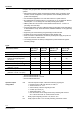
Device combinations with automation stations TX-I/O devices 1) Digital input module 8 or 16 I/O points Universal module without / with local operation and LCD Super universal mod. without / with local operation and LCD Relay module without / with local operation Resistance measuring module (for Pt100 4-wire) Relay module bistable Triac module Power supply module 1.2 A, Fused 10A Bus interface module, Fused 10A Island bus expansion module TX Open module up to 40 / 160 data points 1) Type TXM1.8D, TXM1.
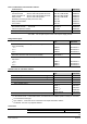
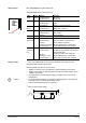
Design 1 2 3 4 5 6 7 8 9 10 11 12 13 14 Positions of keys and batteries Plastic housing Front cover Plug-in screw terminal block (operating voltage) Plug-in screw terminal block (relays) Plug-in screw terminal block (inputs, outputs) LED indicators for relay outputs LED indicators for device and system status Service pin (Network identification) Plug-in screw terminal block (LONWORKS bus, PXC….D only) Network interface RJ45 (BACnet / IP, PXC…-E.
Each relay output has a yellow status LED LED indicators The other LEDs have the follow meanings: RUN FAULT LOW BATT COM INFO SERVICE Service pin Battery change STOP Caution! 9 21 5 Z0 4 _0 1 LED RUN Color Activity Green Continuously off Continuously on FAULT Red Continuously off Continuously on Quick flashes LOW Red Continuously off BATT Continuously on COMM Yellow Continuously off Continuously on Flashing INFO Red SERVICE Red Continuously off (Ethernet) Continuously on Flashing Flashing acc.
Technical data General device data Operating voltage AC 24 V ± 20% (SELV / PELV) or AC 24 V class 2 (US) Operating frequency Power Consumption (depending on field devices) Internal fuse Operating data Processor Memory PXC12/22....D PXC36....D PXC12/22....D PXC36....D Accuracy class Scan cycle Data backup in case of power failure Battery Backup of Realtime Clock Lithium Type BR2032 (optional CR2032) (field replaceable) Battery Backup of SDRAM 1x AA: (field replaceable) Lithium Type FR6/AA: PXCxx.
Universal inputs UI... Configurable by software A/D Resolution (analog in) Measured value inputs Range Input resistance Sensor inputs Temperature sensors LG-Ni 1000, Ni 1000, Pt 1000, T1 Sensor current (continuous current) Resolution Measuring error at 25 °C (Ni 1000, Pt 1000) Measuring error at 25 °C (T1) Signal inputs Contact voltage Contact current Contact transfer resistance Contact isolation resistance Counter inputs Counting frequency (symmetric) Min. closing/opening time incl. bouncing Max.
Plug-in screw terminal Power supply and signals Stranded of solid conductors, 0.25 … 2.5 mm2 or 2 x 1.5 mm2 Single cable lengths and cable types Universal inputs UI... Binary inputs DI... Universal outputs AO… Relay outputs DO… Interface, room unit Cable type Capacitance per unit length Connecting cable Ethernet and PXM20-E Cable type Connecting cable LONWORKS bus Cable type Connecting cable PXM10 Max. 100m where A = 1 mm2 Max. 100 m with diameters 0.6 mm Max. 100m where A 1.
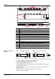
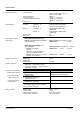
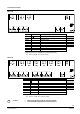
Connection terminals PXC12.D DO1 U1 U2 U3 U4 U5 DO2 U6 U7 DI1 U8 58 59 60 1, 2 3 24 V ~, 4…9 22, 23 DO1, DO2 CLA, CLB U1…U4 U5…U8 DI1, DI2 CP+, CP– HMI HMI / Tool 25 … 30 31 … 36 58 … 60 61, 62 C D HMI / TOOL DI2 61 62 Operating voltage AC 24 V Functional earth CFC IOAddr 2 Digital outputs (Relays) LonWorks-Bus DO1: C=5.1 4 Universal inputs / outputs with Q250 4 Universal inputs / outputs 2 Digital inputs PPS2 bus (for up to 5 QAX...
PXC22.1.D DO1 U1 U2 U3 U4 U9 U10 U11 U12 HMI / TOOL U5 U6 U7 U8 U13 U14 U15 U16 24 V ~, 1, 2 3 Operating voltage AC 24 V Functional earth CFC IOAddr 4 … 21 28, 29 30 ... 38 39 ... 61 80, 81 82 ... 84 DO1 … DO6 CLA, CLB U1 … U6 U7 … U16 CP+, CP– , CD, CS C D HMI HMI / Tool 6 Digital outputs (Relays) DO1: C=5.1 LONWORKS bus 6 Universal inputs / outputs with Q250 xx1: C=4.1 *) 10 Universal inputs / outputs xx7: C=1.1 *) PPS2 bus (for up to 5 QAX...
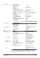
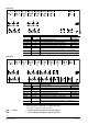
PXC12-E.D U1 U2 U3 U4 U5 U6 U7 DI1 U8 DI2 58 59 60 1, 2 3 24 V ~, 61 62 Operating voltage AC 24 V Functional earth 4…9 25 … 30 31 … 36 58 … 60 61, 62 A DO1, DO2 U1 … U4 U5 … U8 DI1, DI2 CP+, CP– 2 Digital outputs (Relays) 4 Analog inputs / outputs with Q250 4 Analog inputs / outputs 2 Digital inputs PPS2 bus (for up to 5 QAX... room units) Ethernet socket C HMI RJ45 socket for PXM10 CFC IOAddr DO1: C=5.1 xx1: C=4.1 *) xx5: C=1.1 *) DI1: C=3.1 PXC22-E.
PXC22.1-E.D DO1 U1 U5 U2 U3 U6 U4 U7 U9 U8 U13 U10 U11 U14 U15 24 V ~, 1, 2 3 4 … 21 30 ... 38 39 ... 61 80, 81 82 ... 84 U16 Operating voltage AC 24 V Functional earth CFC IOAddr DO1 … DO6 U1 … U6 U7 … U16 CP+, CP– , CD, CS 6 Digital outputs (Relays) DO1: C=5.1 6 Universal inputs / outputs with Q250 xx1: C=4.1 *) 10 Universal inputs / outputs xx7: C=1.1 *) PPS2 bus (for up to 5 QAX...
Pin layout 87654321 Tool socket "HMI" (LONWORKS) 9215Z01 Automation stations for BACnet / IP Pin Description Pin Description 1. 2. 3. 4. 5. 6. 7. 8. Unoccupied Unoccupied G0, GND G/Plus Unoccupied Hot-wired to Pin 8 COM1/TxD COM1/RxD Automation stations for BACnet / LonTalk 87654321 9215Z01 Tool socket "HMI" (Ethernet) Pin Description Pin Description 1. 2. 3. 4. 5. 6. 7. 8.
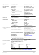
Connecting the field devices STOP Note! In the automation stations described in this data sheet, system neutral (G0) and measuring ground (–) are NOT CONNECTED. For active 4-wire field devices, this connection is made in the device. For active 3-wire field devices, you have to make an additional connection: either on the terminals of the field device or between one of the (–) terminals of the automation station and G0 (in existing plants where there are only 3 conductors installed).
G Damper actuators (e.g. GBB161.1E) AC 24 V G0 G0 G0 G0 G G G U U GBB161.1E N 1 2 2 1 8 9215A06_01 U CP+ U CP- 24V Field device supply from separate transformer AC 24 V G0 9215A07_01 G Magnetic valves (e.g. M3P... + ZM or MX...461...) G0 G0 G0 G G G 24V L N AC 230 V AC 24 V G G0 U U CP+ U CP- STOP U N 1 2 3 4 1 2 Do NOT earth the local transformer G0 (GN) G (GL) YM 4 M3P... + ZM Note! Y MX...461...
Dimensions (All dimensions in mm) PXC12....D and PXC22....D 271,5 50,2 133.5 256 35.5 90 44,3 149,4 7 38,5 50,8 58 9215M01_01 61,7 PXC22.1....D and PXC36.1....D 50 292.6 133.5 278 35.5 45 94 176 150 7 51 73 9215M02_01 77.2 16/18 Siemens Smart Infrastructure PXC….
Disposal The device is considered electrical and electronic equipment for disposal in terms of the applicable European Directive and may not be disposed of as domestic garbage. Dispose of the device through channels provided for this purpose. Comply with all local and currently applicable laws and regulations. Dispose of empty batteries in designated collection points. Lithium batteries: May catch fire, explode or leak.
Published by: Siemens Switzerland Ltd. Smart Infrastructure Global Headquarters Theilerstrasse 1a 6300 Zug Switzerland Tel. +41 41-724 24 24 www.siemens.com/buildingtechnologies © Siemens Switzerland Ltd 2006 Delivery and technical specifications subject to change 18/18 Siemens Smart Infrastructure PXC….