PXC Compact Series Owner's Manual 553-104 2018-10-01 Building Technologies
Copyright Notice Copyright Notice Notice Document information is subject to change without notice by Siemens Industry, Inc. Companies, names, and various data used in examples are fictitious unless otherwise noted. No part of this document may be reproduced or transmitted in any form or by any means, electronic or mechanical, for any purpose, without the express written permission of Siemens Industry, Inc. Warning This equipment generates, uses, and can radiate radio frequency energy.
Copyright Notice To the Reader Your feedback is important to us. If you have comments about this manual, please submit them to: SBT_technical.editor.us.sbt@siemens.com Credits APOGEE, APOGEE GO, InfoCenter Administrator, InfoCenter Report Manager, InfoCenter Server, InfoCenter Suite, and Insight are registered trademarks of Siemens Industry, Inc. Desigo® and Desigo® CC™ are registered trademarks of Siemens Schweiz AG.
Table of Contents Cyber security disclaimer ................................................................................................ 3 How to Use This Manual............................................................................................. 9 Chapter 1—Introduction............................................................................................ 12 PXC Compact Series Product Overview ....................................................................... 12 Ordering Information .
Compressed ROM ............................................................................... 37 Auto-Restore and Database Backup to Flash ..................................... 37 Auto Save ............................................................................................ 38 File System Operations ....................................................................... 38 Random Access Memory (RAM) .........................................................................
TX-I/O Product Range Overview ................................................................................... 84 TX-I/O Module Overview ..................................................................................... 84 TX-I/O Module Product Diagram ......................................................... 85 TX-I/O Module LCD Symbol Chart ...................................................... 86 Address Keys .......................................................................................
RUN LED ........................................................................................................... 107 Communication ................................................................................................. 108 Display ........................................................................................................... 108 Errors ...........................................................................................................
How to Use This Manual How to Use This Manual About This Manual This manual is written for the owner and user of the PXC Compact Series. It is designed to help you become familiar with the PXC Compact and its applications. This section covers manual organization, document conventions and symbols used in the manual, how to access help, related publications, and any other information that will help you use this manual.
How to Use This Manual For Smoke Control Applications Smoke Control Systems Application and Engineering Manual (125-1806). This manual is a comprehensive reference on smoke control applications for APOGEE equipment. It contains all of the various agency requirements and recommended practices of organizations that are widely-recognized in composing standards and testing equipment involved in life safety applications. When Using Insight Software Insight 3.x Documentation. To view Insight 3.
How to Use This Manual Safety Symbols The following table lists the safety symbols used in this manual to draw attention to important information. Symbol Meaning Description NOTICE CAUTION Equipment damage may occur if a procedure or instruction is not followed as specified. (For online documentation, the NOTICE displays in white with a blue background.) CAUTION Minor or moderate injury may occur if a procedure or instruction is not followed as specified.
Chapter 1—Introduction PXC Compact Series Product Overview Chapter 1—Introduction Chapter 1 provides an introduction to the PXC Compact Series and how it is integrated with the APOGEE Automation System.
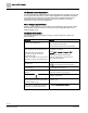
Chapter 1—Introduction PXC Compact Series Product Overview Part Number Description PXC24.2-EF.A PXC Compact, 24 point, BACnet/IP ALN, P1 or MS/TP FLN PXC24.2-EF32.A PXC Compact, 24 point, BACnet/IP ALN, P1 or MS/TP FLN PXC24.2-ER.A PXC Compact, 24 point, BACnet/IP ALN, rooftop PXC24.2-ERF.A PXC Compact, 24 point, BACnet/IP ALN, rooftop, P1 or MS/TP FLN PXC36-E.A PXC Compact, 36 point, BACnet/IP or MS/TP ALN PXC36-EF.
Chapter 1—Introduction PXC Compact Series Product Overview Optional Licenses Product Number Description LSM-FLN License to enable FLN support on models PXC-16-EF.A or PXC-24-EF.A LSM-FLN36.A License to enable FLN support on models PXC36-E.A and PXC36-PE.A LSM-IB36.A License to enable 4 TX-I/O modules on the Island Bus on models PXC36-E.A and PXC36-PE.A LSM-36.A License to enable 4 TX-I/O modules on the Island Bus and FLN support on models PXC36-E.A and PXC36-PE.
Chapter 1—Introduction Compatibility with the APOGEE Automation System Accessories Product Number Description TXA1.K12 One set of address keys, numbers 1-12. TXA1.K24 One set of address keys, numbers 1-24. TXA1.K-48 One set of address keys, numbers 25-48. TXA1.K-72 One set of address keys, numbers 49-72. TXA1.LLT-P100 Labels for TX-I/O, 100 sheets/pack, letter format. TXA1.LH Replacement label holders.
Chapter 1—Introduction Compatibility with the APOGEE Automation System APOGEE P2 and BACnet Product Features Order of Implementation The APOGEE field panel firmware supports the BACnet protocol as follows: ● If both the BACnet and APOGEE protocols have a function, the BACnet function is implemented. ● If APOGEE provides a function that the BACnet protocol does not support, the APOGEE function is retained.
Chapter 1—Introduction Principles of Field Panel Operation The default TCP/IP port number for Virtual AEM communications is 3001. You must specify a UDP port number when using multicast optimization. The default UDP port number is 8. Network Bandwidth BACnet/IP or Ethernet TCP/IP (P2) ALN does not add significantly to your network overhead. Burst conditions for this product occur during: ● Database downloading after coldstart. ● Database uploading. ● Trend data uploading. ● Burst of alarms or COVs.
Chapter 1—Introduction Principles of Field Panel Operation Executing Control Programs The PXC Compact continuously executes a user-defined set of instructions called the control program. This program uses the most recent point values and the most recent clock time. The control program does the following: ● Evaluates control strategies. ● Uses an internal calendar and time clock for time-based functions. ● Updates point values and commands field points according to the program results.
Chapter 1—Introduction Principles of Field Panel Operation ● Checks the current time once per second. – Between 5:00 P.M. and 7:00 A.M., the fan remains OFF. – Between 7:00 A.M. and 5:00 P.M., the control program checks the current value of the temperature and sends the appropriate ON or OFF command to the fan starter. If the ON command is issued, the PXC Compact updates the value of the starter point in its memory to reflect the current state of the fan.
Chapter 1—Introduction APOGEE Automation Networking How does License Manager Work? Field panels can either be ordered with licensed features and functionality pre-loaded, for example, FLN or TX-I/O island bus support, or upgraded to add special features, for example, Integration Drivers, Field Panel GO, and Virtual AEM. NOTE: The installation of some features and licenses require that the field panel be coldstarted, while others do not.
Chapter 1—Introduction APOGEE Automation Networking Automation Level Network The APOGEE Automation Level Network (ALN) provides field panel-to-field panel and Insight workstation-to-field panel communication. The ALN types are: ● P2 RS-485 ALN ● Ethernet TCP/IP ALN ● Remote ALN (Auto-dial and AEM) ● BACnet/IP ALN ● BACnet Master-Slave/Token Passing (MS/TP) ALN Simultaneous ALN Access More than one operator or field panel can access the network at one time.
Chapter 1—Introduction APOGEE Automation Networking Figure 1: Figure. Commanding Over an Automation Level Network. RS-485 P2 Automation Level Network The RS-485 ALN is a proprietary token-passing network that communicates over RS485 cabling. It is Protocol 3 (P3) at and above 38,400 bps, and Protocol 2 (P2) below 38,400 bps. ● An Insight workstation is optional with this ALN.
Chapter 1—Introduction APOGEE Automation Networking Media The RS-485 ALN can communicate over one or more of the following: ● Physical wire (RS-485 cabling) ● Dedicated telephone lines ● Leased-line modems ● Line drivers ● Trunk Isolator Extenders (TIE) ● Fiber Optic Interfaces The trunk system provides connections within buildings or between buildings for multiple field panels and operator workstations. The following figure shows a possible implementation of an RS-485 ALN network.
Chapter 1—Introduction APOGEE Automation Networking Ethernet TCP/IP Automation Level Network The Ethernet Automation Level Network (EALN) uses TCP/IP-based communication over a customer’s Ethernet cabling and IP network to reduce overall system and maintenance costs. Otherwise, system operation is identical to RS-485 ALN installations. ● An Insight workstation is optional with this ALN. ● When an Insight workstation is used, multiple Insight workstations can be defined on the MLN.
Chapter 1—Introduction APOGEE Automation Networking Remote Automation Level Network (Single Field Panel Remote Sites) One PXC Compact can act as a stand-alone field panel. A stand-alone field panel is generally used in remote sites where only one field panel is needed to control the equipment for that site. Communications with the remote site are achieved by using modems or the Virtual APOGEE Ethernet Microserver (AEM).
Chapter 1—Introduction APOGEE Automation Networking BACnet MS/TP Automation Level Network BACnet field panels communicate over a customer’s Ethernet cabling and IP network using the ASHRAE Building Automation and Control Networking (BACnet) MS/TP protocol. ● One Insight workstation can administer up to 64 Ethernet based MS/TP ALNs. ● Up to 10 BACnet MS/TP ALN field panels can reside on an MS/TP network segment (1000 maximum per Insight workstation). Network segments must be physically separated.
Chapter 1—Introduction APOGEE Automation Networking Field Level Network The APOGEE Field Level Network (FLN) is a data communications network that passes information between an FLN device or devices and an Automation Level Network (ALN) device, usually within one building. FLNs consist of devices that communicate using P1 or MS/TP. ● P1 devices can include Terminal Equipment Controllers (TEC), Fume Hood Controllers (FHC) and other vendor equipment, such as ABB Speed Drives, which contain Protocol 1.
0 Chapter 2—Hardware Features 16- and 24-Point Compact Series Diagram Chapter 2—Hardware Features Chapter 2 describes the PXC Compact Series components and functions, as well as the enclosure used for the PXC field panel series.
Chapter 2—Hardware Features 0 16- and 24-Point Compact Series Diagram PXC-16 and PXC-24 Features and Symbols. Terminal Block Connection 1 Label Indicates 24V ~ Supply voltage, 24 Vac input. 2 System neutral. 3 Functional earth. 4 through 12 (PXC-16) 4 through 18 (PXC-24) Digital Output relay. A (22 through 24) RS-485 port. +– B 10B/100B Ethernet port. C USB Device port. 25, 27, 28 Universal Input (+) (UI1 through UI3). 26, 29 – Signal Common.
0 Chapter 2—Hardware Features 36-Point Compact Series Product Diagram PXC-16 and PXC-24 Status LEDs. Status LED Label Indicates RS-485 TX RS-485 TX (yellow) Flashing - Transmitting information over the RS-485 RS-485 P2 or BACnet MS/TP ALN or P1 or MS/TP FLN (depending on how the port is defined). OFF or ON solid - No device, no connection, or bad connection.
Chapter 2—Hardware Features 0 36-Point Compact Series Product Diagram PXC-36 Features, Symbols, and Status LEDs. Terminal Block Connection Label Indicates 3 Functional earth. 4 through 27 Digital Output relay. A 10B/100B Ethernet port. B USB Device port. 30, 32, 33, 35, 36, 38 Super Universal (+). (X1 through X6) 31, 34, 37 – Signal Common. 39, 41, 50, 52, 53, 55, 56, 58, 59, 61, 62, 64, 65, 67, 68, 70, 71, 73 40, 51, 54, 57, 60, 63, 66, 69, 72 Universal Input/Output (+).
0 Chapter 2—Hardware Features Supported Point Types PXC-36 Features, Symbols, and Status LEDs. Status LEDs Label Indicates RS-485 RX A RX (yellow) Flashing - Receiving information over RS-485 P1 (FLN 1) or MS/TP FLN. B RX (yellow) Flashing - Receiving information over RS-485 P2 or BACnet MS/TP ALN or P1 (FLN 2) (depending on how the port is defined). A RX or B RX OFF or ON solid - No device, no connection, or bad connection. DO XX DO 29 through DO 36 ON - Relay Energized.
Chapter 2—Hardware Features Supported Point Types 0 PXC-24 Supported Point Types.
0 Chapter 2—Hardware Features Compact Series Backup Batteries PXC-36 Supported Point Types. Configurable Points Super Universal (X) Points 1-6 Point Type Digital Output Universal Input/Output (U) Points 7-24 Dedicated Points Digital Input (DI) Points 25-28 • •4 Binary/Digital Output Digital Output (DO) Points 29-36 1) Platinum 1K 375 or 385 alpha. 2) Siemens, Johnson Controls, and DIN Standard Nickel. 3) 10K and 100K Type 2 and 10K Type 3. 4) Requires an external relay.
Chapter 2—Hardware Features Compact Series Backup Batteries 0 AA Battery CAUTION Batteries Failure to change DEAD alkaline battery will eventually result in battery leakage, causing permanent damage and loss of building control. Failure to change a DEAD lithium battery will result in loss of trend and database if not backed up, causing loss of data or building control. Establish a preventative maintenance schedule based on expected battery usage and life cycle.
0 Chapter 2—Hardware Features Compact Series Backup Batteries Coin Cell Battery The coin cell battery is present on all PXC-36 Compact Series and on Version 2 or later of PXC-16 and PXC-24. The hardware version is indicated in the Product Number as follows: ● The number after PXC16 or PXC-24 indicates the hardware version. For example, PXC24.2-PE.A is Version 2. ● No number after PXC16 or PXC-24 is Version 1 hardware. For example, PXC24PE.A is Version 1.
Chapter 2—Hardware Features 0 Memory Memory Size and Typical Battery Backup Time Memory Size and Typical Battery Backup Time.
0 Chapter 2—Hardware Features Memory – When auto-restore is enabled, a coldstart does not result in the same downtime as with earlier revisions of APOGEE Firmware. Because there is no waiting on a full download from the backup system, the database is restored from flash so quickly that there is little to no downtime. However, the accumulated trend data is deleted from memory. – Database restoration from flash is disabled by default.
Chapter 2—Hardware Features Communication Connections 0 USB Media Support ● ● Support for USB mass storage devices (Memory sticks or USB hard drives). Backup of database, storage for graphics, Web Server upgrades Random Access Memory (RAM) Synchronous Dynamic Random Access Memory (SDRAM) is the working memory of the PXC Compact.
0 Chapter 2—Hardware Features Communication Connections Human-Machine Interface (HMI)/Tool Port The Human-Machine Interface (HMI)/Tool port provides RS-232 compliant communications through a quick-connect RJ-45 jack. The HMI port supports the following functionality: ● Connecting a machine interface device, such as an operator terminal or a textbased operator terminal, to the PXC Compact. ● Executing firmware flash upgrades. ● 1200 bps to 115.2 Kbps communication is supported.
Chapter 2—Hardware Features 0 Communication Connections PXC-36 RS-485 A and B Ports The following table outlines the configuration options for the PXC-36 RS-485 “A“ and “B“ ports.
0 Chapter 2—Hardware Features Communication Connections NOTE: A P1 FLN license must be installed in order to use Wireless FLN. NOTE: The PXC Compact on P1 is not supported on the Wireless FLN. The following additional hardware is required to implement the Wireless P1 FLN with the PXC Compact Series: ● Field Level Network Transceiver (FLNX) ● Field Panel Transceiver (FPX) See the section Minimum Firmware Revision Required for information on the firmware revision required to implement Wireless P1 FLN.
Chapter 2—Hardware Features 0 Compact Series Specifications Compact Series Specifications Dimensions (L × W × D) PXC-16 and PXC-24 10.7" × 5.9" × 2.45" (272 mm × 150 mm × 62 mm) PXC-36 11.5" × 5.9" × 3.
0 Chapter 2—Hardware Features Compact Series Specifications Electrical Power Requirements 24 Vac ±20% input @ 50/60 Hz Power Consumption (Maximum) PXC-16: 18 VA @ 24 Vac PXC-24: 20 VA @ 24 Vac PXC-36: 35 VA 24 Vac AC Power and Digital Outputs NEC Class 1 Power Limited Communication and all other I/O NEC Class 2 Contact Closure Sensing Dry Contact/Potential Free inputs only Does not support counter inputs Digital Input Digital Output Class 1 Relay Analog Output 0 to 10 Vdc Universal Input (UI)
Chapter 2—Hardware Features 0 BACnet Compact Series Specifications Operating Environment Ambient operating temperature 32°F to 122°F (0°C to 50°C) Ambient operating temperature with rooftop -40°F to 158°F (-40°C to 70°C) (extended temperature) option PXC-16 and PXC-24: 5 to 95% rh non-condensing Relative Humidity PXC-36: 5 to 95% rh non-condensing Mounting Surface PXC-16 and PXC-24: Direct equipment mount, building wall, or structural member PXC-36: Building wall or a secure structure Agency Lis
0 Chapter 2—Hardware Features BACnet Compact Series Specifications Processor, Battery, and Memory Processor and Clock Speed PXC-16 and PXC-24: Freescale MPC852T, 100 MHz PXC-36: Freescale MPC885, 133 MHz Memory PXC-16 and PXC-24: 24 MB (16 MB SDRAM, 8 MB Flash ROM) PXC-16/24 “F” and “F32”: 40 MB (32 MB SDRAM, 8 MB Flash ROM) PXC-36: 80 MB (64 MB SDRAM, 16 MB Flash ROM) NOTE: See the Configuration and Sizing Guidelines document for supported memory size.
Chapter 2—Hardware Features 0 BACnet Compact Series Specifications Electrical Contact Closure Sensing Dry Contact/Potential Free inputs only Does not support counter inputs Digital Input Digital Output Class 1 Relay Analog Output 0 to 10 Vdc Universal Input (UI) and Universal Input/Output (U) Analog Input Voltage (0-10 Vdc) Current (4-20 mA) 1K Ni RTD @ 32°F 1K Pt RTD (375 or 385 alpha) @ 32°F 10K NTC Type 2 or Type 3 Thermistor @ 77°F 100K NTC Type 2 Thermistor @ 77°F Digital Input Pulse Accumula
0 Chapter 2—Hardware Features BACnet Compact Series Specifications Agency Listings UL864 UUKL Smoke Control Equipment (except UEC and rooftop models) UL864 UUKL7 Smoke Control Equipment (except UEC and rooftop models) CAN/ULC-S527-M8 (except rooftop models) UL916 PAZX (all models) UL916 PAZX7 (all models) UL FCC Compliance CFR47 Part 15, Subpart B, Class B Australian EMC Framework European EMC Directive (CE) European Low Voltage Directive (LVD) Agency Compliance RoHS Compliant Product meets OSHPD Spec
Chapter 2—Hardware Features 0 HOA (Hand-Off-Auto) Upgrade Kits ● ● A USB-to-RS-232 adaptor may be needed for UL Listed modems or UL Listed printers that are not configured for USB communication. The modem may be located inside the PX Series enclosure. Example ALN Configuration for Smoke Control Applications The RS-485 ALN does not have the same restrictions as the Ethernet ALN for smoke control. Namely, Ethernet requires UL listed switches and routers.
0 Chapter 2—Hardware Features HOA (Hand-Off-Auto) Upgrade Kits ● ● The HOA module can be used to override outputs and monitor inputs. The HOA mapping and definition of a logical point in the database can be done in any order. ● The HOA is hot-swappable. The module can be installed without powering down the controller and interrupting facility operations. ● The HOA module can also be remote mounted on the inside or outside of an enclosure door, using an optional accessory sold separately.
Chapter 2—Hardware Features 0 HOA (Hand-Off-Auto) Upgrade Kits Using the HOA Switches LED and Override Status Placing Device into Override To manually override the present value of an analog or digital output on the PXC Compact, you must engage the appropriate switch assigned to the desired equipment to be controlled. Pressing the center of the switch enables the Override mode and energizes the Yellow Override status LED.
0 Chapter 2—Hardware Features HOA (Hand-Off-Auto) Upgrade Kits Manual Control Settings for Analog Outputs 7 70% 7 15.2 8 80% 8 16.8 9 90% 9 18.4 10 100% 10 20 Digital Output Override Pressing the switch causes the output to turn ON and the Green I/O status LED is ON at 100%. Pressing the switch causes the output to turn OFF and the Green I/O status LED is OFF at 0%. The Yellow Override status LED will flash momentarily for any change in value.
Chapter 2—Hardware Features PXC Compact on P1 0 Default Mapping For each type of PXC Compact (16, 24 and 36) that supports HOA and each HOA unit (8, 16 rooftop or 16 non-rooftop UL 864), there is a default mapping between each button and physical point. The default mapping provides Plug-and-Play functionality.
0 Chapter 2—Hardware Features PXC Compact on P1 receive and process P1 request messages from an APOGEE tool, such as WCIS, connected to the HMI port. See the section Minimum Firmware Revision Required for information on the firmware revision required to implement PXC Compact operation on P1 FLN. P1 Mode Operation ● ● ● ● ● ● ● ● Since an ALN network connection is not present in P1 mode, PXC Compact applications that support point access across the ALN are limited to local points only.
Chapter 2—Hardware Features PXC Compact on P1 0 The following additional subpoints are automatically added to the field panel point team when the PXC Compact is in P1 mode: ● APPLICATION, DAY.NGT, and OVRD TIME, must be present in every P1 FLN device. ● APPLICATION is the currently active P1 application at the PXC Compact on P1. DAY.NGT and OVRD TIME are available for user-defined use with PPCL. ● BATT reflects the status of the lithium battery. ● BATT2 reflects the status of the Real Time Clock.
0 Chapter 2—Hardware Features PXC Compact on P1 Default Applications Both the PXC-16 and PXC-24 support a default (slave mode) application, which is useful if a custom application has not yet been loaded into the PXC Compact on P1 in an Application ISB file. ● If a PXC Compact is set up in P1 mode without an application number, the default application is used. ● For the PXC-16 the default application is 3916; for the PXC-24, the default application is 3924.
Chapter 2—Hardware Features 0 PXC Compact on P1 Language selection and user account timeout settings are configurable using an operator workstation or HyperTerminal at the field panel’s HMI. All PXM10S/T preferences are panel-specific and stored in the local panel configuration data. NOTE: For more information on creating and configuring user accounts, see the APOGEE P2 ALN Field Panel User's Manual (125-3019) or the APOGEE BACnet ALN Field Panel User's Manual (125-3020) (125-3019 or 125-3020).
0 Chapter 2—Hardware Features PXC Compact on P1 Requirements System Requirements The PXM10S and PXM10T modules can be used with Compact platforms (PXC-36, PXC-24, and PXC-16), as well as with the PXC Modular field panels. NOTE: The PXM10S or PXM10T module firmware uses the proprietary Siemens PXM10 protocol to communicate with the host field panel. ● ● ● All hardware must be installed. Power must be available to all devices.
Chapter 2—Hardware Features PXC Compact on P1 0 Operator Display Layout Display screen – Displays splash screen with either PXM10S or PXM10T module, device Firmware Revision, field panel Firmware Revision number, and Cimetrics BACstac revision number. Cursor position is indicated by either a right-angled bracket (>) or inverted text color, depending on field panel type and revision.
0 Chapter 2—Hardware Features PXC Compact on P1 Alarm button – Press to display the unacknowledged alarm list. The Alarm LED flashes when an alarm is triggered in the local field panel. Pressing the Alarm button always takes you directly to the unacknowledged alarm list. The three states of the Alarm LED are: ● ● ● Alarm LED On – if any object is in the Alarm or Failed condition, but no object is in the unacknowledged condition, the LED light is ON solid.
Chapter 2—Hardware Features PXC Compact on P1 0 Figure 7: INFO for Alarms Press ESC to close alarm window without affecting the alarm. Operator Display Menu Tree Siemens Industry, Inc.
0 Chapter 2—Hardware Features PXC Compact on P1 Main Menu Structure All menu screen captures in this manual reflect the PXM10S module. Not all menu options/features shown are available with the PXM10T module. NOTE: A solid DOWN arrow in the top right corner of the display screen indicates more menu options are available and a solid UP arrow indicates more items are available after the last highlighted item. Figure 8: Main Menu Alarms - Allows you to view and acknowledge alarms and failures/faults.
Chapter 2—Hardware Features 0 PXC Compact on P1 Logging In Automatic Login The PXM10S or PXM10T automatic login feature must be configured using the host field panel’s HMI port. Only one user account can be flagged as the automatic login account. NOTE: Default user account login information for PXM10S or PXM10T is on a per ALN account basis. If your network contains an assortment of field panels with Firmware Revisions earlier than 2.8.6/3.2.
0 Chapter 2—Hardware Features PXC Compact on P1 Prompt/Field Language ID Option/Entry Description Trend N (No_access) R (Read_only) C (Command) E (Edit) (default setting) Application N (No_access) R (Read_only) C (Command) E (Edit) (default setting) PPCL N (No_access) R (Read_only) C (Command) E (Edit) (default setting) FLN devices N (No_access) R (Read_only) C (Command) E (Edit) (default setting) Equipment Scheduler N (No_access) R (Read_only) C (Command) E (Edit) (default setting) System
Chapter 2—Hardware Features PXC Compact on P1 Prompt/Field Option/Entry Description N Disable automatic logoff. Password Expire Limit 0 0 to 365 days. Use for PXM10Tiny AutoLogin (Y/N) Y Enable automatic login. N Disable automatic login. Example >User initials : tiny >Account name : PXM10TINY---------------------->Password : ?????--------->Verify password : ?????--------->System, User namespace : U >Access group(s) : 1..
0 Chapter 2—Hardware Features PXC Compact on P1 Figure 9: Automatic Login Submenu Menu/Submenu Step Splash screen/logo Press the dial. Login Description Rotate the dial to highlight Automatic Login. Login menu displays. Press the dial to select Automatic Login. System logs you into the Main menu of the module. Figure 10: Main Menu Manual Login Do the following to manually log in to the PXM10S or PXM10T module. The default language for manual login is U.S. English.
Chapter 2—Hardware Features PXC Compact on P1 Menu/Submenu Step Description Press the dial to select each character. Repeat until you enter the complete user name. NOTE: If you make a mistake selecting a character, press ESC to return to the previous character. 0 Press the dial twice to move to the PWD fields. For PWD, rotate the dial highlight each character. Press the dial to select a character. Repeat until you enter the complete password.
0 Chapter 2—Hardware Features PXC Compact on P1 Menu/Submenu Step Description Main Rotate DIAL to highlight Logoff. Press DIAL/OK to and select Logoff. Confirm Logoff Are you sure? Displays the Logoff submenu. Rotate DIAL to highlight Yes or No. Press DIAL/OK to make selection. Confirms logoff and returns to splash screen. NOTE: If you press ESC, you are prompted with the same Confirm Logoff screen.
Chapter 2—Hardware Features PXC Compact on P1 Menu/Submenu Step Main Rotate DIAL to highlight Alarms. Alarms 0 Description Press DIAL/OK to select Alarms. Displays the Alarms menu. Press DIAL/OK to select All Alarms. Displays a list of unacknowledged alarms and alarms that have been acknowledged, but not yet reset. Proprietary version also displays “Failures” submenu. Rotate DIAL to highlight a point in alarm. Press DIAL/OK to accept selection.
0 Chapter 2—Hardware Features PXC Compact on P1 Menu/Submenu Step Main Rotate DIAL to highlight Alarms. Alarms Unacknowledged Alarms Description Press DIAL/OK to select Alarms. Displays the Alarms menu. Rotate DIAL to highlight Unacknowledged Alar. Displays a list of unacknowledged alarms. Press DIAL/OK to select Unacknowledged Alar. Displays a list of unacknowledged alarms and alarms. Rotate DIAL to highlight desired point in alarm. Press DIAL/OK to select a point.
Chapter 2—Hardware Features 0 PXC Compact on P1 Menu/Submenu Step Description Main Rotate DIAL to highlight Points. Press DIAL/OK to select Points. Points Displays the Points menu. Press DIAL/OK to highlight desired point. Press DIAL/OK to select point. Rotate DIAL to highlight the last point (bottom of screen), and then rotate DIAL once more. Refreshes the screen and displays the previous screens last highlighted point, as well as the next series of points.
0 Chapter 2—Hardware Features PXC Compact on P1 Commanding Points Do the following to change the point value and command the points in the field panel. These steps also apply to commanding TEC subpoints. Figure 21: Point Action Command Submenu Menu/Submenu Step Description Main Rotate DIAL to highlight Points. Press DIAL/OK to select Points. Displays the Points menu. Points Press DIAL/OK to highlight desired point. Displays the Point Action Command submenu.
Chapter 2—Hardware Features PXC Compact on P1 0 Figure 23: Edit Command Point Value Submenu Releasing Points Do the following to change a point priority and release a point. Figure 24: Point Action Release Priority Submenu Menu/Submenu Step Description Main Rotate DIAL to highlight Points. Press DIAL/OK to select Points. Points Displays the Points menu. Rotate DIAL to highlight desired point. Press DIAL/OK to select point. BACnet Point Action Displays the Point Action Release Priority submenu.
0 Chapter 2—Hardware Features PXC Compact on P1 Menu/Submenu Step P2 Point Action: Rotate DIAL to highlight Release Priority. Description Press DIAL/OK to select Release Priority. Rotate DIAL to select Yes or No. Press DIAL/OK. This releases the priority to NONE. Press ESC. Returns you to the previous menu without changing the point priority. Figure 25: Release Priority Value Submenu Configuring Point Monitor NOTE: This application and its sub-features are only available with the PXM10S module.
Chapter 2—Hardware Features PXC Compact on P1 Menu/Submenu Step Main Rotate DIAL to highlight Point Monitor. Point Monitor 0 Description Press DIAL/OK to select Point Monitor. Displays the Point Monitor menu. Rotate DIAL to highlight Configure. Displays all available points at the field panel. Press DIAL/OK to select Configure. Edit Pt Monitor Rotate DIAL to highlight desired point. Displays black background, allowing you to edit field. Press DIAL/OK to select point.
0 Chapter 2—Hardware Features PXC Compact on P1 Menu/Submenu Step Description Edit Pt Monitor Rotate DIAL to select desired point. Displays all available points and subpoints at the field panel. Subpoints Rotate DIAL to select subpoint. Displays a list of subpoints associated with the selected point. Press DIAL/OK to select Y or N. Y=Yes; point is monitored. N=No; point is not monitored. (This is the default setting.) Press ESC. Returns you to the Point Monitor menu.
Chapter 2—Hardware Features PXC Compact on P1 0 Displaying Monitored Points Automatic logoff occurs after a predetermined amount of inactivity, however: ● The Point Monitor continues to display points and refreshes the Display screen every four seconds. ● You can scroll the Point Monitor, but the function keys (INFO, ESC, Alarm) are disabled. ● If you press any of the key functions, the login splash screen prompts you to login. Do the following to display monitored points.
0 Chapter 2—Hardware Features PXC Compact on P1 Figure 33: Adjust Brightness Submenu Menu/Submenu Step Main Rotate DIAL to highlight Settings. Description Press DIAL/OK to select. Settings Displays the Settings menu. Press DIAL/OK to highlight Brightness. Press DIAL/OK to select Brightness. Brightness Displays the Brightness submenu. Rotate DIAL to highlight Adjust Brightness. Press DIAL/OK to select Adjust Brightness. Rotate DIAL to select a value. Valid brightness values are 0 through 100.
Chapter 2—Hardware Features PXC Compact on P1 Menu/Submenu Step Main Rotate DIAL to highlight Settings. 0 Description Press DIAL/OK to select. Displays the Settings menu. Settings Press DIAL/OK to highlight and Displays the Color submenu. select Color. Color Rotate DIAL to highlights and select Adjust Color. Rotate DIAL to toggle between Displays the backlight color you choose. Blue and White color. Press DIAL/OK to select. Applies the value and returns you to the previous menu. Press ESC.
0 Chapter 2—Hardware Features PXC Compact on P1 Menu/Submenu Step Timeout Rotate DIAL to highlight and select Adjust Timeout. Description Rotate DIAL to select a value. Valid Timeout values are 0 through 240 seconds. Press DIAL/OK to select. Applies the value and returns you to the previous menu. Press ESC. Returns you to the Settings menu without applying the new value.
Chapter 2—Hardware Features 0 PXC Compact on P1 ● ● ● ● ● ● ● ● ● ● ● ● ● ● ● Only visible to the Web Server when defined as a FLN device. Operates on the FLN without replication. Cannot be programmed from an ALN device, if added as an FLN device. Recognized as a Siemens device. Exposes application number and default subpoint. Supports failure detection of the UEC by other nodes. Limited support of failure detection of other nodes by the UEC, only when defined as a node of interest.
0 Chapter 2—Hardware Features PXC Compact on P1 Processor, Battery, and Memory Processor and Clock Speed Freescale MPC852T, 100 MHz Memory 24 MB (16 MB SDRAM, 8 MB Flash ROM) Serial EEPROM 4 KB Battery backup of Synchronous Dynamic (SD) RAM (field replaceable) AA (LR6) 1.5 Volt Alkaline (non-rechargeable) 180 days (accumulated) Typical Accumulated Battery Life of Compact UEC: 16MB SDRAM Std (alkaline): 180 days Rooftop (Extended Temperature) Models: 330 days (accumulated) AA (LR6) 3.
Chapter 2—Hardware Features 0 PXC Compact on P1 Electrical Analog Input Voltage (0-10 Vdc) Current (4-20 mA) 1K Ni RTD @ 32°F 1K Pt RTD (375 or 385 alpha) @ 32°F 10K NTC Type 2 or Type 3 Thermistor @ 77°F 100K NTC Type 2 Thermistor @ 77°F Digital Input Pulse Accumulator Contact Closure Sensing Dry Contact/Potential Free inputs only Supports counter inputs up to 20 Hz Analog Output Voltage (0-10 Vdc) Current (4-20 mA) Digital Output (requires an external relay) 0 to 24 Vdc, 22 mA max.
0 Chapter 2—Hardware Features TX-I/O Product Range Overview TX-I/O Product Range Overview TX-I/O™ is a range of I/O modules, with associated power and communication modules, for use within the APOGEE System. The I/O modules communicate between the PXC Modular or the PXC-36 and the related devices in the building services plant. The TX-I/O product range includes the following: ● Eight types of I/O modules, which act as signal converters. ● TX-I/O Power Supply for the TX-I/O modules.
Chapter 2—Hardware Features TX-I/O Product Range Overview 0 TX-I/O Module Product Diagram TX-I/O Module Symbols and Status LEDs LED, Symbol, or Feature 1 Address key and module status LED (green) LED or Symbol - Indication Module status as a whole (as opposed to the I/O points). ON Normal operation. 24 Vac (supply voltage) input present; fuse is intact. OFF Error. - No 24 Vac (supply voltage) input. - Fuse is blown.
0 Chapter 2—Hardware Features TX-I/O Product Range Overview TX-I/O Module Symbols and Status LEDs LED, Symbol, or Feature LED or Symbol Flashing or pulsing Indication - Override action - Remote override - Output: Local override is off, operation is not possible. - Input: Operation is not possible. 8 LCD signal panel - Only on a TX-I/O modules with –ML suffix. 9 Local override switch - Only on a TX-I/O with –M or –ML suffix.
Chapter 2—Hardware Features TX-I/O Product Range Overview 0 TX-I/O LCD Panel by Point Type. Point Type (Displays in LCD Bottom Row) Normal Operation (Displays in LCD Top Row) Analog Input, Current Low or high value Analog Input, Resistance Temperature Analog Input, Voltage Low or high value Analog Output, Current Low or high value Analog Output, Voltage Low or high value Digital Input, Counter The picture can't be displayed.
0 Chapter 2—Hardware Features TX-I/O Product Range Overview When replacing the plug-in I/O module, the address key must first be swiveled outward. This switches the load off but values remain saved in the PXC Modular, PXC36, or P1 BIM. The key remains plugged into the terminal base so that the PXC Modular, PXC-36, or P1 BIM can communicate the required function to the new I/O module.
Chapter 2—Hardware Features TX-I/O Product Range Overview 0 Island Bus Expansion Module The Island Bus Expansion (IBE) module provides the following functions for the island bus: Product TX-I/O Bus Communication Function Island Bus Expansion Module (TXA1.
0 Chapter 2—Hardware Features PX Series Enclosures and Service Boxes ● Routes the bus signal between DIN rails (+24 Vdc Communication Supply (CS) and Communication Data (CD) signals). Supply Terminal Connections ● ● ● ● 24 Vdc is supplied to terminals one and four (CS) and to both ends of the TX-I/O bus connector for distribution to connected TX-I/O modules and external devices. 24 Vac is passed through an internal fuse from terminals three and four (system neutral) to the male TX-I/O bus connector.
Chapter 2—Hardware Features PX Series Enclosures and Service Boxes 0 The service box assemblies consist of the following: ● Chassis for mounting inside enclosure. ● ON/OFF circuit breaker for transformer. ● Two Class 1 power limited 24 Vac outputs, which include one terminal for earth ground for use inside enclosure only. ● One Class 2 output with circuit breaker to distribute up to 96 VA for use outside the enclosure. ● Wire cover for field connections. ● Duplex Service Outlet (115 Vac models only).
0 Chapter 2—Hardware Features PX Series Enclosures and Service Boxes Figure 41: PX Series Service Box (115V), 19-inch enclosure. Figure 42: PX Series Service Box Connectors. ● ● 92 | 118 Siemens Industry, Inc. Building Technologies Each Service Box distributes the total 24 Vac power provided to the plug-in terminations on the left side. – Two Class 1 power-limited terminations distribute up to the total power to controllers and power supplies inside the same enclosure.
Chapter 2—Hardware Features PX Series Enclosures and Service Boxes 0 Product Numbers Product Number Description PXA-SB115V192VA PX Series Service Box—115V, 24 Vac, 50/60 Hz, 192 VA PXA-SB115V384VA PX Series Service Box—115V, 24 Vac, 50/60 Hz, 384 VA PXA-SB230V192VA PX Series Service Box—230V, 24 Vac, 50/60 Hz, 192 VA PXA-SB230V384VA PX Series Service Box—230V, 24 Vac, 50/60 Hz, 384 VA PXA-ENC18 18" Enclosure (Utility Cabinet) (UL Listed NEMA Type 1 Enclosure) PXA-ENC19 19” Enclosure (UL Liste
0 Chapter 2—Hardware Features PX Series Enclosures and Service Boxes Building wall or structural member (Do not mount on HVAC components or any other vibrating surface.
Chapter 2—Hardware Features PX Series Enclosures and Service Boxes 0 CAUTION If the enclosure is mounted under a wire trough or any other obstruction, provide a minimum vertical clearance of 2 inches (50.8 mm) to allow for installation and removal of the enclosure door. Siemens Industry, Inc.
0 Chapter 2—Hardware Features PX Series Enclosures and Service Boxes ● ● ● 96 | 118 Siemens Industry, Inc. Building Technologies Space between door panel and opening obstruction must be at least 11 inches (279.4 mm) to allow for door removal at 40 degrees, or 28 inches (711 mm) with a cabinet mounting at least 19 inches (483 mm) from the left side wall to allow door to completely open at 135 degrees.
Chapter 3—Applications Operator Interface Chapter 3—Applications Chapter 3 describes the program and applications provided with or available for the PXC Compact Series.
Chapter 3—Applications Operator Interface Field Panel Web Server The Field Panel Web Server encompasses the following operator applications: ● Graphical Monitoring and Control ● Network Layout ● System Status Bar ● Alarm Status and Acknowledgement ● Point Commanding ● Scheduling ● Graphical Trend Display ● Reporting ● Configuration and Customization ● Remote Notification Graphics ● ● ● Customized system graphics Live animation of equipment Real-time point values and status updates Network Layout ● ● ●
Chapter 3—Applications Powers Process Control Language (PPCL) Control Program and Point Database Configuration and Customization ● ● ● Custom Welcome Page User interface translatable to any browser-supported language Ability to customize font sizes and display colors Powers Process Control Language (PPCL) Control Program and Point Database The control programs and point database are stored in RAM.
Chapter 3—Applications Applications Applications Applications are an important part of the energy management capabilities of your system.
Chapter 3—Applications Applications Daylight Saving Time The Daylight Saving Time (DST) functionality adjusts the system time to match the daylight saving time change-over. If your area uses daylight saving time, this feature offers a convenient method to automatically adjust the system clock. Equipment Scheduling Equipment Scheduling is designed to provide 365-day, time-based control of a space in a facility. The basic design of this application begins with a definition of the space, called a zone.
Chapter 3—Applications Applications Trend Data Collection Trending is a function that records point data over time. Trend data is either collected when the current point value changes by a specified amount (the trend COV limit), or point values are recorded after the system waits a specific amount of time and then the process is repeated.
Chapter 3—Applications Customized Applications Customized Applications Some PXC Compact Series applications are created in the Powers Process Control Language (PPCL). These applications use PPCL statements and additional hardware to perform customized operations or functions in your system.
Chapter 4—Troubleshooting Service Information Chapter 4—Troubleshooting NOTE: The following information is for qualified service personnel only. Chapter 4 describes corrective measures you can take if you encounter a problem with a PXC Compact Series controller. If you encounter a symptom or a problem not covered in this manual, contact your Siemens Industry representative.
Chapter 4—Troubleshooting Service Information Electrostatic Discharge An electrostatic discharge (ESD) wrist strap is generally not required when installing or servicing a PXC Compact. However, if the field panel is installed in a very dry environment where a high static discharge is likely, an ESD wrist strap is recommended.
Chapter 4—Troubleshooting Troubleshooting Compact Field Panels Reinstalling the Mounting Tabs Do the following to reinstall a DIN mounting tab: 1. Place the wire spring clip into the pocket in the channel for the mounting tab. 2. Make sure the mounting tab is face down. 3. Working from the center (inside) of the base, slide the mounting tab into the channel. (See the following figure.) NOTE: The end with the screw hole slides into the channel first. Figure 44: Reinstalling a DIN Mounting Tab.
Chapter 4—Troubleshooting Troubleshooting Compact Field Panels BATT LOW LED The BATT LOW LED is on or the battery low warning is displayed at the operator's terminal. CAUTION If you do not have a current backup, save the database before continuing. 1. Check that the mylar insert was removed from the AA (LR6) battery holder. 2. Check for polarity (+ to +) and (- to -). 3. Check that the battery is properly seated in the battery holder. 4. Replace the battery.
Chapter 4—Troubleshooting Troubleshooting Compact Field Panels 2. Verify that the cable from the field panel to the operator's terminal is properly connected at both ends. 3. Open the enclosure and verify that both ends of the HMI extension cable are properly connected. 4. Unplug the extension cable and plug directly into HMI port. The RUN LED is off. 1. Verify that power is connected. 2. Check the service box and transformer ON switches. 3. If power is ON, verify that the application firmware has booted.
Chapter 4—Troubleshooting Troubleshooting the TX-I/O Island Bus PXC Compact defaults to Ethernet ALN but continues to display parameters for RS-485 P2 ALN. 1. Generate the Field Panel Configuration report by entering the following at the HMI: S, H, F, D (System, Hardware, Fieldpanels, Display). 2. Verify the field panel settings on the Field Panel Configuration report (such as the ALN baud rate for P2 ALN or an IP address for Ethernet TCP/IP ALN). 3.
Chapter 4—Troubleshooting Troubleshooting the TX-I/O Island Bus CAUTION The TX-I/O™ island bus must extend from the male bus connector of the TX-I/O Power Supply or Bus Connection Module. • The TX-I/O Power Supply and Bus Connection Module only supply 24 Vac to I/O modules on the male bus connector. • I/O modules on the female bus connector of the TX-I/O Power Supply or Bus Connection Module do not receive power and have a fault condition.
Glossary Glossary The glossary contains terms and acronyms that are used in this manual. 1 100Base-TX: Fast Ethernet network implementation. 100Base-TX stands for 10Mbps baseband twisted-pair cable. The “X” stands for 100Base-X, the IEEE identifier for the media system used by 100Base-TX. 10Base-T: Ethernet network implementation. 10Base-T stands for 10Mbps baseband twisted-pair cable.
Glossary D Device ID: Uniquely identifies a device object on the BACnet Inter network. Device Instance Number: A number assigned to a BACnet device (for example, a BACnet field panel) that uniquely identifies it on the BACnet/IP network. Device port: A USB Device port supports a generic serial interface for an HMI or Tool connection. Device Specific Name: A textual representation of a BACnet object name that meets the APOGEE naming standard of 30 alphanumeric characters or less.
Glossary Intrinsic Alarming: BACnet alarming that incorporates alarm destinations (via Notification Classes) within a single alarm message. M multicast: Destination IP address that represents one or more interfaces. IP datagrams sent to a multicast address will be sent to all hosts participating in this multicast group. N notification class: Notification Class supports enable/disable based on the day of week and time of day and the alarm priority for all points associated with it.
Glossary Transmission Control Protocol/Internet Protocol (TCP/IP): Protocol suite developed by the U.S. Department of Defense to link dissimilar computers across different kinds of networks. TCP/IP is the transport protocol employed by the Internet and is commonly used on Ethernet networks. U unbundle: Describes the action of entering a point that resides in an equipment controller's database into the field panel's database so that it can be monitored and controlled from the field panel.
Index Index 1 10B/100B Ethernet port........................................... 40 16- and 24-point Compact on P1 FLN ............................................................ 42 product diagram ................................................... 29 status LEDs .......................................................... 29 16-point Compact supported point types ........................................... 32 2 24-point Compact supported point types ...........................................
Index Daylight Saving Time (DST) .................................. 101 DHCP server .......................................................... 16 DNS node name format .......................................... 17 Domain Name Server ............................................. 16 E electrical specifications ................................ 44, 46, 82 electrostatic discharge (ESD) ................................ 105 Equipment Scheduling ..........................................
Index network bandwidth ............................................... 17 network security ................................................... 17 required IP addresses .......................................... 16 Virtual AEM........................................................... 17 time functions ....................................................... 101 trend data collection .............................................. 102 troubleshooting 24 Vac LED ...............................................
Issued by Siemens Industry, Inc. Building Technologies Division 1000 Deerfield Pkwy Buffalo Grove IL 60089 +1 847-215-1000 Document ID: 553-104 Edition: 2018-10-01 © Siemens Industry, Inc., 2018 Technical specifications and availability subject to change without notice.