
User Manual

84 / 134
Siemens Synco™ living CE1C2740en
Building Technologies Commissioning the system 13.12.2010
Test radio connections
The radio connections between the central apartment unit and the following
devices can be tested at any time:
• Room temp sensor
• Room unit
• Radiator control actuator
• Heating circuit controller (per channel)
• Multi-controller (per channel)
• RF repeater
• Meteo sensor
• Water detector (QAX913 only)
• Handheld control (QAX913 only)
• Consumption data interface (per channel)
Press briefly the binding or the multifunction button on the device. Select first
the desired channel on the heating circuit controller, multi-controller and con-
sumption data interface using the channel selection button. For the handheld
control, briefly press both upper buttons.
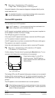
If connection works, the central apartment unit beeps three times. If the cen-
tral apartment unit is on the default picture or one of the info pages, an addi-
tional window with the respective device information is displayed. The window
can be hidden again by pressing the
Menu/ok or the Esc button.
Wiring test
We recommend to carry out a wiring test on the connected components after
completing configuration and connecting the devices.
The current states of the inputs are displayed:
• The current temperature value at the sensor inputs.
• 0/1 with input contacts (0: contact open, 1: contact closed).
• 0..100% at DC 0..10 V inputs.
During the wiring test, each of the outputs can be set to a certain value:
• 0..100% (corresponding to DC 0..10 V) for heat demand DC 0..10 V.
• Off/on with relay outputs (off: relay contact open, on: relay contact closed).
During the wiring test, the application is not active. Safety-related func-
tions are switched off. Switch the relay outputs off again.
RF adapter plugs KRF96x do not react to the values set in the wiring
test.
The RF adapter plug state, however, can be switched over any time
using the local button on the RF adapter plu.
The wiring test for the different inputs and outputs is available in the following
menus: