Modbus Air Pressure Sensor with I/O extension QBM3700..
Contents Legal note ............................................................................................................3 Safety notes in the data sheet................................................................................3 1 1.1 1.2 1.3 1.4 Installation .................................................................................................4 Mounting .....................................................................................................
Legal note Safety notes in the data sheet Legal note Legal note concept This guide includes notes that must be followed for your own personal safety as well as to prevent damage to property. Notes dealing only with damage to property do not have the warning triangle and use the signal word NOTICE and an exclamation point.
1 Installation Mounting 1 Installation 1.1 Mounting NOTICE Hint Mount the sensor in a location that is easy to open the cover and access the terminals, DIP switches and view the LEDs. Proceed as follows to mount the sensor to a surface: ● Screw the sensor at the 2 brackets (on the device sides) to the mounting surface. ● Keep the following guidelines min. 75 134 5.5 Fig.
Installation Quick release fasteners and detached cover 1 1.
1 Installation Connecting tubes 1.3 Connecting tubes Connect the tubes Avoid loops 1.4 Wiring 1.4.1 Starting point Electrical grounding Note the following grounding situation of the QBM3700...
1 Installation Wiring ● ● ● ● Consequence QBM3700.. uses a non-isolated RS485-Interface. The reference of RS485 transceiver is connected to GND. All GND pins are on the same potential. If the Climatix controller and QBM3700.. are connected to the same power source, take care to avoid incorrect wiring between 24 V input and GND. The document "Modbus communication" (J3960) provides profound information on Modbus grounding. 1.4.2 Power supply Terminal 24V≂ →, ,24V≂ ← Note 1.4.
1 Installation Wiring 1.4.4 Signal wiring The following graphics illustrate all signal types of a QBM3700... 1.4.4.1 Analog inputs Analog inputs for passive sensors Application Connecting passive temperature sensors.
Installation Wiring 1.4.4.2 1 Analog outputs Analog outputs with voltage signal Application Connecting devices that are controlled with a 0...
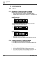
2 Commissioning Address 2 Commissioning 2.1 Address 2.1.1 DIP switches (Climatix and other controllers) Use DIP switches to adjust the Modbus address and for termination. ● The DIP-switches have priority over register 4x0764 (Modbus address). ● The Modbus address (register 4x0764) is valid as soon as all DIP switches are on '0'. ● Changes to DIP switches are effective after 5 seconds.
2 Commissioning Fault detection, correction or reset 1. Press and hold the push button for 5...10 seconds. 2. As soon the button is released the status LED lights up orange. The QBM3700.. temporarily receives address 246 to connect. The baud rate is automatically recognized. The format changes to 1-8-E-1. The master writes the Modbus parameter. Master writes '1' into register 4x0768 ("Bus config command"). 3. QBM3700.. gets its final Modbus address by the application/HMI.
2 Commissioning Fault detection, correction or reset Value Value Error code (register 4x0002) 8 Calculation error 9 Extended error 10 EEPROM protection active 11 Configuration error Reliability pressure sensor (register 4x0004 + 4x0006) Reliability analog inputs (register 4x0008 + 4x0010) Configuration error Configuration error LED status indication Color Status Function Red Blinking, 1 second on, 5 seconds off Internal error Red Blinking, 0.
Engineering Implementing volume flow measurement 3 3 Engineering 3.1 Implementing volume flow measurement Implementing volume flow measurement In addition to normal (differential) pressure measurement, the QBM3700.. provides volume flow measurement (i.e. used with 3rd party controllers). Flow is a volume over time. It is related to differential pressure according to the following formula: Flow measurement with QBM3700.. is set up in an application as follows: 1.
3 Engineering Addr. Description 4x0001 Type Modbus registers Unit Scaling R/W Area Data type 1 R uint16_t 9705 = 1x 500 Pa 9710 = 1x 1250 Pa 9720 = 1x 2500 Pa 4x0002 Error code 1 R uint16_t 4x0003 Analog output coupling 1 R/W 0 = Analog output coupled with differential pressure sensors = default uint16_t 1 = Analog output coupled as defined in 4x0028/4x0058 (setpoint) 4x0004 Differential pressure 1- Reliability 1 R uint16_t 4x0005 Differential pressure 1 - Value See config.
3 Engineering Modbus registers Differential pressure 1 Addr. Description 4x0035 Unit Scaling R/W Area Data type Reliability. 1 R uint16_t 4x0036 Value 1 R uint16_t 4x0037 Unit 1 R/W 0 = Pa = (Default) uint16_t 1 = PSI 2 = mmHG 3 = mmH2O 4x0038 Value [Pa] Pa 1 R uint16_t 4x0039 Value [PSI] PSI 0.
3 Engineering Modbus registers Differential pressure 2 Addr. Description 4x0065 Unit Scaling R/W Area Data type Reliability. 1 R uint16_t 4x0066 Value 1 R uint16_t 4x0067 Unit 1 R/W 0 = Pa = Default uint16_t 1 = PSI 2 = mmHG 3 = mmH2O 4x0068 Value [Pa] Pa 1 R uint16_t 4x0069 Value [PSI] PSI 0.
3 Engineering Modbus registers Modbus Settings (as per Climatix) Addr. Description 4x0764 Modbus addressing Unit Scaling R/W Area Data type 1 R/W 1 ≤ VAL ≤ 247 uint16_t 255 = Default 4x0765 Baud rate 1 R/W 0 = Auto (Default) uint16_t 1 = 9600 2 = 19200 3 = 38400 4 = 57600 4x0766 Format 1 R/W 0 = 1-8-E-1 (Default) uint16_t 1 = 1-8-O-1 2 = 1-8-N-1 3 = 1-8-N-2 4x0768 Bus config. command 1 R/W 0 = Ready (Default) uint16_t 1 = Load 2 = Discard Addr.
4 Maintenance Fused mode analog outputs 4 Maintenance 4.1 Fused mode analog outputs QBM37.. Are supplied with a fused mode. This prevents damage caused by an interruption in Modbus communications. The analog outputs are switched to DC 0 V for interruptions to communications >60 seconds. 4.2 Zero reset Perform the zero reset without tubes. Afterwards reconnect the tubes Blue 10...
Supplemental information 5 5 Supplemental information Document title Topic Document no: Datasheet: Modbus air pressure sensor with I/O extension: QBM3700.. Functions, use, technical data, terminals, dimensions and Modbus registers A6V11684000 Mounting instructions: Differential Pressure Sensors QBM3700..
Issued by Siemens Switzerland Ltd Smart Infrastructure Global Headquarters Theilerstrasse 1a CH-6300 Zug +41 58 724 2424 www.siemens.com/buildingtechnologies © Siemens Switzerland Ltd, 2019 Technical specifications and availability subject to change without notice.