
User Manual


4/4
Siemens Building Technologies Room sensor QFA65.1 CM1N1850E
HVAC Products 14.07.2003
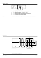
Internal diagram
r.H.
1850G01
M(5)
LG-Ni 1000
G0(1) G(2)B(6) U(3)
G (2) System potential AC 24 V
G0 (1) System and relative humidity measuring neutral
U (3) Measuring signal DC 1...9 V for 10...90 % r.h.
B (6) Measuring signal LG-Ni 1000 (passive) for temperature
M (5) Temperatur sensor measuring neutral
The number in parentheses corresponds to the terminal label on the terminal block.
Dimensions
90
100
32
56
60
9,5
56
60
1850M01
4,2
Dimensions in mm
Notes:
ã 2000 Siemens Building Technologies AG