
User Manual


Siemens Building Technologies CM1N5485E / 10.1998
Landis & Staefa Division 3/6
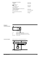
Spatial arrangement of detection zones for an installation height of 3 m above the floor.
- 3
- 2
- 1
0
1
2
3 m
- 3 - 2 - 1 0 1 2 3 m
- 3 - 2 - 1 0 1 2 3 m
5485Z02
3 m
2
1
0
30˚
(diagonal 23˚)
• People must be present within the detection zone.
• The presence detector must be located such that it clearly detects all people.
• The presence detector cannot see through glass. Hence, glass doors and windows
confine the detection zone.
• Interference by partitions, shelves, plants, etc., must be avoided.
• The detection zone has the shape of a pyramid. The area covered on the floor is
exactly a square (see illustration). The size of the square is solely determined by the
detector's height above the floor.
When fitted to the ceiling, the detector is automatically out of reach and thus safe
against vandalism.
• Moving objects (curtains covering radiators, revolving doors, etc.) that are too close to
the presence detector (within 2 m).
• Objects that warm up rather quickly (lamps, air inlets, radiators, etc.) and that are too
close to the presence detector.
• Direct solar radiation hitting the presence detector.
• The detector locations specified in the planning documentation must not be changed.
• There is a choice of fitting the detector on a recessed conduit box (using a single
conduit box of 58 mm dia.) and surface mounting (using a standard bezel of 50 mm
depth).
• To avoid damage to the detector, only the power part should be fitted at first. The
actual detector should be installed only at the time the plant is commissioned. The
optical part of the detector should be handled with care. No pressure must be exerted
on the plastic insert!
The unit is supplied complete with installation instructions.
Detection zones
Checklist for planning
Detection of movements
Vandalism
Possible sources of error
Fitting notes