
Data Sheet for Product

7/12
Siemens Duct air quality sensors QPM11.., QPM21.. CE1N1962en
Smart Infrastructure 2020-03-03
· In the event of VOCfailure, DC 10 V or 5 V or 20 mA will be present at signal output
X1 (after 60 seconds)
· In the event of CO
2
failure, DC 10 V or 5 V or 20 mA will be present at signal output
X1 (after 60 seconds)
· In the event of CO
2
or VOC failure, DC 10 V or 5 V or 20 mA will be present at signal
output X2 (after 60 seconds)
· Should the temperature sensor become faulty, 0 V or 0 mA will be present at signal
output X2
· Should the temperature sensor become faulty, 0 V or 0 mA will be present at signal
output X3, and the humidity signal at signal output X2 will increase to DC 10 V or 5 V
or 20 mA (after 60 seconds)
· Should the humidity sensor become faulty, DC 10 V or 5 V or 20 mA will be present
at signal output X2 (after 60 seconds), and the temperature signal will remain active
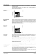
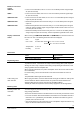
With sensors type QPM2102D, QPM2160D and QPM2162D, the measured values can
be read on an LCD. The following measured values are displayed:
- CO
2
: In ppm
- CO
2
+ VOC: As a bar chart: 4 bars
X2 = 2 V or 1 V or 7,2 mA
20 bars X2 = 10 V or 5 V or 20 mA
- Temperature: In °C or °F
- Humidity: In % r.H.
Accessories
Name Type reference
Filter cap (for replacement) AQF3101
Engineering notes
To power the sensor, a transformer for safety extra low-voltage (SELV) with separate
windings for 100 % duty is required. When sizing and protecting the transformer, local
safety regulations must be complied with.
When sizing the transformer, the power consumption of the duct sensor must be taken
into consideration.
For correct wiring, refer to the Data Sheets of the devices with which the sensor is
used.
The permissible cable lengths must be observed.
When laying the cables, it must be observed that the longer the cables run side by side
and the smaller the distance between them, the greater the electrical interference.
Shielded cables must be used in environments with EMC problems.
Twisted pair cables are required for the secondary supply lines and the signal lines.
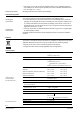
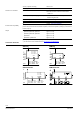
Mounting notes
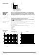
To ensure degree of protection IP54 resp. IP65, the sensor must be fitted with the cable
entry pointing downward!
The sensor should be mounted in locations where it can be easily accessed for service.
· If used in connection with steam humidifiers, the distance to the humidifier must be a
minimum of 3 m. If permitted by the installation, the distance should be as great as
possible, but no more than 10 m
· The sensing elements in the immersion rod are susceptible to impact and shock. Any
impact or shock should therefore be avoided
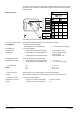
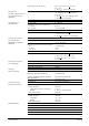
Behavior in the event
of fault
QPM1100
QPM2…
QPM2102/2102D
QPM2160/2160D
QPM2162/2162D
Display of measured
values
Cable routing and
cable
selection
Mounting location and
orientation
Note!