
Data Sheet for Product

Technical Instructions QPM Series Indoor Air Quality Duct Sensors
Document Number CE1N1962
July 26, 2019
Page 4 Siemens Industry, Inc.
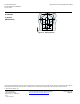
Mechanical Design
The duct air quality sensor consists of housing, printed circuit board, connection
terminals, mounting flange and immersion rod with measuring probe.
The two-sectional housing is comprised of base and removable cover (without display:
snap-on design, with display: screwed fastening). The measuring circuit and the setting
elements are located on the printed circuit board inside the cover, the connection
terminals on the base.
The humidity and temperature sensing elements are located at the end of the
measuring probe and are protected by a filter cap.
Immersion rod and housing are made of plastic and are rigidly connected.
The sensor is fitted with the mounting flange supplied with the sensor. The flange is
placed over the immersion rod and then secured at the required immersion length.
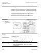
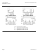
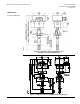
Setting Elements
NOTE: The setting
elements are
located inside the
cover.
Figure 3. Setting Elements.
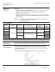
Measuring Range
QPM2100
Meaning of the different jumper positions:
• For CO
2
Only:
Jumper in the middle position (R2) = 0 to 2000 ppm (factory setting).
R1 and R3 are not used.
QPM2102/QPM2102D
• For CO
2
/VOC, jumpers determine VOC Sensitivity:
− Jumper in the left vertical position (R1) = VOC sensitivity "low".
− Jumper in the middle position (R2) = VOC sensitivity "normal"
(factory setting).
− Jumper in the right vertical position (R3) = VOC sensitivity "high".
QPM2160/QPM2160D,
QPM2162/QPM2162D
• For the CO
2
and temperature, jumpers determine temperature range:
− Jumper in the upper position (R1) = -31°F to 95°F (−35 to 35°C).
− Jumper in the positions (R2 or R3) = 32°F to 122°F (0 to 50°C)
(R2, factory setting).