
Data Sheet for Product

QPM Series Indoor Air Quality Duct Sensors Technical Instructions
Document Number CE1N1962
July 26, 2019
Siemens Industry, Inc. Page 5
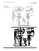
Output Signal Selection
• O1 = 4 to 20 mA
• O2 = 0 to 10V
• O3 = 0 to 5V
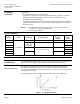
Active Test Function
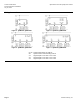
Jumper for the measuring range in the horizontal position:
The signal output delivers the values according to the Test function active table (see
Figure 3).
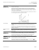
Temperature Display
Changeover
Meaning of the different jumper positions:
− Jumper in the right vertical position = °C (factory setting).
− Jumper plug in the left vertical position = °F.
Troubleshooting
QPM2100/QPM2100D
QPM2102/QPM2102D
• In the event of CO
2
or VOC failure, 10 Vdc, 5 Vdc, or 20 mA will be present at signal
output X2 (after 60 seconds).
QPM2160/QPM2160D
QPM2162/QPM2162D
• If the temperature sensor becomes faulty, 0V or 0 mA will be present at signal output X2.
• If the temperature sensor becomes faulty, 0V or 0 mA will be present at signal output
X3, and the humidity signal at signal output X2 will increase to 10 Vdc, 5 Vdc, or
20 mA (after 60 seconds).
• If the humidity sensor becomes faulty, 10 Vdc or 5 Vdc will be present at signal
output X2 (after 60 seconds), and the temperature signal will remain active.
Display of Measured
Values
With sensors QPM2102D, QPM2160D and QPM2162D, the measured values can be
read on an LCD. The following measured values are displayed:
• CO
2
: In ppm
• CO2 + VOC: As a bar chart 4 bars X2 = 2V, 1V or 7.2 mA,
20 bars X2 = 10V, 5V or 20 mA
• Temperature: In degrees C or F
• Humidity: In % rh
Disposal
The device is considered electrical and electronic equipment for disposal in terms of the
applicable European Directive and may not be disposed of as domestic garbage.
• Dispose of the device through channels provided for this purpose.
• Comply with all local and currently applicable laws and regulations.
Engineering Notes
• The sensor must be powered by a transformer for Safety Extra Low-Voltage (SELV)
with separate windings, suited for 100% duty. It must be sized and fused in
compliance with local safety regulations.
• When sizing the transformer, the power consumption of the sensor must be taken
into consideration. For information about wiring, see the Technical Instructions of the
devices with which the sensor is used.
• Observe maximum permissible cable lengths.
Cable Routing and
Selection
• When laying the cables, it should be considered that electrical interference increases
the longer the cables run parallel and the smaller the distance between them.
• Use shielded cables on applications with EMC problems.
• For the secondary power lines and signal lines, use cables with twisted pairs.