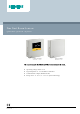
Fine Dust Room Sensors QSA2700D / QSA2700 / AQS2700 The sensors acquire the PM2.5 and PM10 concentration in the room. ● ● ● ● A6V11160938_en--_c 2019-04-10 Operating voltage AC/DC 24 V Signal output DC 0...10 V for PM2.5 and PM10 Communicative output, Modbus RS485 Range of use 0…50 °C / 5…95% r.h.
Use The fine dust room sensor is designed to measure and transmit indoor concentrations of PM2.5 and PM10. ● 0…10 V and Modbus output ● Configurable Modbus parameters ● Quick configuration (on-event addressing) with Siemens ClimatixTM controller ● QSA2700: – 3-color LED service indication ● QSA2700D: – 2.4-inch color LCD screen for PM2.
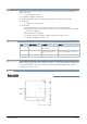
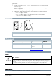
1 Hole for wiring (top) for surface mounting 2 [QSA2700 only] LED 3 [QSA2700D only] LCD display 4 (power supply for display only) 5 [QSA2700D only] Proximity sensor 6 Push button 7 Hole for wiring (bottom) for surface mounting 8 Hole for attaching the mounting plate to the housing 9 Air outlet 10 Air inlet LED colors and patterns (QSA2700) Color Pattern Description Green Permanently on Working properly, Modbus configured Yellow Permanently on Working properly, Modbus with factory
Enter addressing mode and configuration workflow via push button Press the LED Action 1…5 s Constant red Press and hold the button 5…10 s LED off Release the button More details button for Entering the addressing mode, LED flashes yellow for 30 s. ● Address is set to 246 temporarily. Communication is established automatically when: ● Baud rate is 19200 (default). ● Format is 1-8-E-1 (default). ● Address is 246. Then: ● Master writes the Modbus parameters.
QSA2700D: 1. From the normal display page, press the push button for 2-10 s to enter the Modbus parameter page. 2. Then, following the display indication, press the button for 2-10 s to enter the page for Modbus configuration. 3. Select the desired operation by short pressing the button. 4.
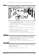
Twisted pair cables are required for the secondary supply lines and the signal lines. Mounting ● ● ● ● ● ● ● ● ● The sensor is suitable for conduit box mounting, dry wall mounting (with mounting hole for wires concealed) and surface mounting. The recommended height is 1.2-1.5 m above the floor, especially for type with display. Do not mount the sensor in recesses, shelves, behind curtains or doors, or above heat sources. Avoid direct solar radiation.
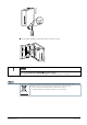
2. Take off the module by hand and replace it with a new one. NOTICE Turn off the device before replacing the sensor module. If not possible, insert a new sensor module 10 s after the old one is removed. Disposal The device is considered electrical and electronic equipment for disposal in terms of the applicable European Directive and may not be disposed of as domestic garbage. Siemens Smart Infrastructure ● Dispose of the device through channels provided for this purpose.
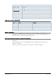
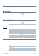
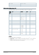
Technical data Power supply Operating voltage AC 24 V ±20% / DC 13.5…35 V Frequency 50/60 Hz @ AC 24 V Power consumption 4 VA Functional data for PM2.5 Measuring range (selectable) ● 0…500 μg/m3 ● 0…300 μg/m3 ● 0…100 μg/m3 ● 0…50 μg/m3 Unit to unit variability Max of ±15 μg/m3 and ±15% of reading @ 25 °C and 50% r.h. Analog output signal, (terminal U1) DC 0...
Transmission Format (start bit - data bits – parity – stop bit) 0=1-8-E-1 (default) / 1=1-8-O-1/ Bus Termination No Reset button Yes 2=1-8-N-1 / 3=1-8-N-2 Modbus registers (Software version 1.2.12) The following Modbus registers are used in software version 1.2.12 and previous. Holding Register (16-bit) No. Name Description Default R/W 257 PM2.
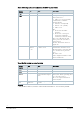
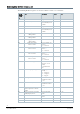
Modbus registers (Software version 1.3.13) The following Modbus registers are used in software version 1.3.13 and later. Holding Register (16-bit) No. Name Description Default R/W 9 PM2.5 value Range: 0…500 R 10 PM2.5 reliablility 0: No error; 1: Bad reliability or not available R 11 PM10 value Range: 0…500 R 12 PM10 reliablility 0: No error; 1: Bad reliability or not available R 201 PM2.5 (μg/m3): Min. value in rolling 24hours R 202 PM2.
Holding Register (16-bit) No. Name Description Default R/W 765 Baud rate 1= 9600bps; 2 R/W 0 R/W 0 R/W 2 = 19200bps; 3 = 38400bps; 4 = 57600bps 766 Transmission format (start bit – data bits – parity – stop bit) 0 = 1-8-E-1; 1 = 1-8-O-1; 2 = 1-8-N-1; 3 = 1-8-N-2 768 Bus configuration command 0 = Ready; 1 = Load; 2 = Discard Remarks: ● The register number is counted from 1. ● The precondition for valid displays of temperature (register 217) and r.h.
Housing protection class Degree of protection of housing IP30 Operation conditions Temperature 0…50 °C Humidity 5...95% r.h. (no condensation) Storage and transportation conditions Temperature -20…70 °C Humidity 0…95% r. h. (no condensation) Electromagnetic compatibility CE standard EN 60730-1 Immunity EN 61 000-6-2 Emissions EN 61 000-6-3 EU conformity declaration A6V11277342 *) Standards *) The document can be downloaded at http://siemens.com/bt/download.
Error info Error info 0-10 V output Replace sensor module Present 0 V (2 Value of register 209 s) and 10 V (2 s) changes from 0 to 1 one by one in turn Red permanently on Communicati on error Value of register 209 Present 0 V (5 s) and 10 V (5 s) changes from 0 to 2 one by one in turn Red flashing (0.5 s on / 0.5 s off) Warning for Present the possible measured value inaccurate measurement Modbus LED indication Value of register 209 remains 0 without change LCD Red / yellow flashing (0.
Issued by Siemens Switzerland Ltd Smart Infrastructure Global Headquarters Theilerstrasse 1a CH-6300 Zug Tel. +41 58 724 2424 www.siemens.com/buildingtechnologies 14 Siemens Smart Infrastructure Document ID A6V11160938_en--_c Edition 2019-04-10 © Siemens Switzerland Ltd, 2017 Technical specifications and availability subject to change without notice.