
Product Overview


QVE1900U
Technical Instructions
Document No. 155-778
May 14, 2013
Flow Switch
Siemens Industry, Inc.
Description
The QVE1900U Flow Switch is used in HVAC installations to monitor the flow of fluids in
hydronic heating and cooling systems.
Product Number
QVE1900U
Operation
There are three terminals inside the enclosure:
• Red = Common
• Blue = Normally Closed (NC)
• White = Normally Open (NO)
When there is no flow, or when the flow rate is insufficient to activate the switch, the circuit
between the red and blue terminals is closed, and the circuit between the red and white
terminals is open. When the flow rate increases to a level sufficient to activate the switch
mechanism, the circuit between the red and blue terminals will open, and the circuit between
the red and white terminals will close.
The switch activation points can be adjusted via the + / - screw inside the enclosure.
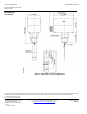
Mechanical Design
The unit consists of a base, paddle, and body with a 1" MNPT system connection.
The base houses the microswitch, electrical terminals, and adjusting screw (for switch-
on/switch-off point), a paddle holder, and an opening for the cable entry. Four paddles are
included that can be trimmed to accommodate different pipe diameters.
The cover is secured to the base with two screws.