RDF300, RDF300.02 RDF340, RDF600 RDF300.02/VB RDF400.01, RDF600T Flush-mounted room thermostats for Fan coils, with LCD RDF300… / RDF340... / RDF400… / RDF600… Basic Documentation Edition 4.
Table of contents 1 1.1 1.2 1.3 1.3.1 1.3.2 1.3.3 2 2.1 2.2 2.3 2.4 2.5 3 4 4.1 4.2 4.3 4.4 4.5 4.6 4.6.1 4.6.2 4.6.3 4.7 4.8 4.9 4.10 4.11 4.12 4.13 4.14 5 5.1 5.2 5.3 6 6.1 6.2 6.2.1 6.2.2 6.2.3 7 7.1 8 Index About this document ........................................................................... 3 Revision history ..................................................................................... 3 Reference documents ............................................................................
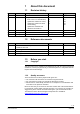
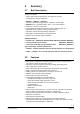
Edition 4.0 3.0 Date 2020-02-21 2014-10-15 2.0 1.1 1.0 Oct 2012 28 Aug 2008 10 July 2008 1 About this document 1.1 Revision history Changes · Added RDF300.02/VB · Update overcurrent protection from a fuse to a circuit breaker; · Update the notation for valves; · Update the warning for wiring and mounting; · Update the standards and directives for RoHS 2.0. Added RDF600… Left column in table First edition 1.2 Ref. N3076 B3076 M3076 M3163 Section 4.4 4.6 5.1 6.2 8 Pages 1, 6 12 17 34 37 42 All 4.
1.3.3 Document use / request to the reader Before using our products, it is important that you read the documents supplied with or ordered at the same time as the products (equipment, applications, tools, etc.) carefully and in full. We assume that persons using our products and documents are authorized and trained appropriately and have the technical knowledge required to use our products as intended.
2 Summary 2.1 Brief description The devices support: – 2-pipe, 2-pipe with electrical heater and 4-pipe fan coil units – Compressors in DX-type equipment · RDF300… / RDF400… / RDF600… : AC 230 V operating voltage, on/off or 3-position control outputs · RDF340 AC 24 V operating voltage, DC 0…10 V control outputs · Output for 3-speed or 1-speed fan · Two multifunctional inputs for keycard contact, external sensor, etc.
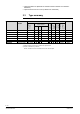
· Optional backlit LCD (RDF300.02 / RDF300.02/VB / RDF400.01 / RDF600 / RDF600T) · Optional infrared remote control ( RDF400.01 / RDF600T) 2.3 RDF300 RDF300.02 RDF300.02/VB RDF400.01 RDF340 RDF600 RDF600T RDF300 RDF300.02 S55770-T427 RDF400.01 RDF340 S55770-T291 S55770-T292 AC 230V AC 230V AC 230 V AC 230V AC 24V AC 230V AC 230V ü ü ü ü ü ü ü ü ü ü ü ü ü ü ü ü ü conduit box 2) square square ü ü ü ü Suitable DC 0..
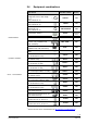
2.4 Equipment combinations Product number Data sheet *) QAH11.1 1840 QAA32 1747 QAP1030/UFH 1854 Condensation monitor QXA21.. A6V10741 072 Electromotoric ON/OFF actuator SFA21... 4863 MVI…/MXI… 4867 SUA… 4832 STA23... 4884 STP23... 4884 SSA31... 4893 SSP31… 4864 SSB31... 4891 SSC31… 4895 SSA61.. 4893 SSC61.. 4895 SSP61.. 4864 SSB61.. 4891 SAS61.. 4581 SAT61.. 4584 STA63 4884 STP63 4884 Type of unit Cable temperature sensor or changeover sensor, cable length 2.
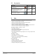
2.5 Accessories Designation Changeover mounting kit (50 pcs/package) Plastic mounting spacer for flushmounted thermostats RDF3... RDF400… for increasing the headroom in the conduit box by 10 mm Conduit box for flush-mounted thermostat RDF3... RDF400… 3 Data Sheet Product no. ARG86.3 N3009 ARG70.
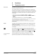
General note 4 Functions 4.1 Temperature control The setting of he control parameters (P01 etc., mentioned throughout the document) is described in section 4.14. The controller acquires the room temperature via built-in sensor, external room temperature sensor (QAA32), or external return air temperature sensor (QAH11.1), and maintains the setpoint by issuing actuator control commands to heating and/or cooling equipment.
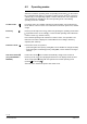
4.2 Operating modes Select the controller's operating mode via operating mode button on the controller or operating mode input (e.g. keycard occupancy sensor, when X1 or X2 set to 3 (P38, P40)). A corresponding setpoint is used to maintain the room temperature at the desired level depending on the active operating mode. The following operating modes are available: Comfort mode In Comfort mode, the controller maintains the setpoint which can be adjusted via the +/- buttons.
4.3 Room temperature setpoints Comfort mode The setpoint in Comfort mode can be adjusted via the +/- buttons. Setpoint limitation For energy saving purposes, the setpoint adjusting range can be limited to minimum (P09) and maximum (P10). P09 < P10 · If the minimum limit P09 is set lower than the maximum limit P10, both heating and cooling are adjustable between these two limits. P09 ≥ P10 · For heating or cooling applications (e.g.
4.4 Applications The controller supports following applications, which can be configured by DIP switches on the inner side of the controller front panel. Depending on the type, on/off or modulating control outputs are available. Applications for fan coil systems Application and output signal, DIP switches, diagram · RDF300... ON RDF400... 1 2 RDF600...
Applications for Universal systems Application and output signal, DIP switches, diagram RDF400... 1 2 RDF600... Chilled / heated ceiling modulating, DC 0…10 V (heating or cooling) B2 RDF300... ON ON RDF340 1 2 · Chilled / heated ceiling ON/OFF (heating or cooling) with electrical heater D3 T RDF400... 1 D3 T V1 2 RDF600... · Chilled / heated ceiling modulating, DC 0…10 V (heating or cooling) with electrical heater B2 RDF300...
Applications for heat pump systems Application and output signal, DIP switches, diagram RDF300... ON RDF400... 1 2 RDF600... · 1-stage compressor ON/OFF (heating or cooling) with electrical heater D3 RDF300... ON RDF400... 1 2 RDF600... 3181S32 1-stage compressor ON/OFF (heating or cooling) 3181S31 · D3 T T B1 B1 E1 T · 1-stage compressor ON/OFF (heating and cooling) N1 T N1 RDF300... ON RDF400... 1 2 3181S35 RDF600...
Compressor-based application Use with one 1-stage compressor for heating and cooling, or cooling only, or heating only. Universal applications Thanks to a flexible fan control, the RDF3xx / RDF4xx can also be used in universal applications, e.g. fan coil-based cooling and floor heating, or chilled ceiling and electrical heater etc. See also section 4.8 “Fan control”. 4.5 Automatic H/C changeover Additional features The water temperature acquired by the changeover sensor (QAH11.1 + ARG86.
Avoid damage from moisture In very warm and humid climates, the fan can be run periodically or continuously at a low fan speed (e.g. in empty apartments or shops) in Economy mode by setting parameter P61 to avoid damage from moisture due to a lack of air circulation. See also section 4.8 “Fan control”, under “Fan kick function”. Minimum output on-time/off-time Limit the on/off switching cycle to protect the compressor and reduce wear and tear.
4.6 Control sequences The controller can be used in systems featuring: · · · · Heating or cooling mode (P01=0 or P01=1) Manual heating/cooling changeover (P01=2) Automatic heating/cooling changeover (P01=3) Heating and cooling mode (e.g. 4-pipe system) (P01=4) The relevant modes are available and can be adjusted via commissioning parameter “Control sequence” P01, depending on the selected application. Sequence Parameter Mode P01 = 0 Heating mode P01 = 1 Cooling mode *) 2-pipe with el.
4.6.1 2-pipe fan coil unit On/off output Heating or cooling In 2-pipe applications, the controller controls a valve in heating/cooling mode with changeover (automatic or manual), heating only mode, or cooling only mode. Cooling only is factory set (P01=1). Control sequence on/off output The diagram below shows the control sequence for on/off (2-position) control.
4.6.2 2-pipe fan coil unit with electrical heater Heating or cooling with electrical heater In 2-pipe applications with electrical heater, the controller controls a valve in heating/cooling mode with changeover, heating only mode, or cooling only mode plus auxiliary electrical heater. Cooling only is factory set (P01=1) with enabled electrical heater (P13). Electrical heating, active in cooling mode In cooling mode, the valve receives an OPEN command if the acquired temperature is above the setpoint.
Note For better temperature control performance with 2-pos electrical heater, we suggest to set the switching differential heating (P30) to 1K. The diagram below shows the control sequence for continuous PI control. Control sequence modulating output Heating mode Cooling mode (automatic changeover=heating or heating only) (man. /auto.
4.6.3 4-pipe fan coil unit In 4-pipe applications, the controller controls two valves in heating and cooling mode, heating/cooling mode by manual selection, or heating and cooling mode with changeover. Heating and cooling mode (P01=4) is factory set. 4-pipe application with manual selection The heating or cooling output can be released via operating mode selector button if parameter P01 is set to manual (P01=2).
The diagram below shows the control sequence of a continuous PI control.
4.7 Overview of control outputs Control outputs Different control output signals are available depending on the controller type. Control output on/off Type reference RDF300… RDF400… RDF340… RDF600 RDF600T 3-position Y11, Y21 (2) Y11, Y21 (2) Y11/Y21 (1) Y11/Y21 (1) Y11, Y21 (2) Y11, Y21 (2) Y11/Y21 (1) Y11/Y21 (1) DC 0…10 V Y10, Y20 (2) ( ) Number of outputs on/off control signal (2-position) The valve or compressor receives the OPEN/ON command via control output Y11 or Y21: 1.
4.8 Fan control The fan operates in automatic mode or at the selected speed with manual mode. In automatic mode, the fan speed depends on the setpoint and the current room temperature. When the room temperature reaches the setpoint, the control valve closes and the fan switches off or stays at fan speed 1 (parameter P60) Factory setting for P60,: · RDF600... fan Off in dead zone · RDF3..., RDF4...
Fan operation as per heating/cooling mode, or disabled Fan operation can be limited to be active only in cooling or heating mode, or even totally disabled via control parameter “Fan operation” P52. When fan operation is disabled, the fan symbol on the display disappears and actuating the fan button has no influence. This function allows for using the controller in universal applications such as floor heating with fan coil cooling etc.
Clean fan filter reminder The clean fan filter reminder function counts the fan operating hours and displays message “FIL” to remind the user to clean the fan filter as soon as the threshold is reached. This does not impact controller operations, which continues to run normally. The service interval can be set via parameter P62. The clean filter reminder is reset when the operating mode is manually set to Protection respectively .
4.9 Multifunctional input The controller offers two multifunctional inputs X1 and X2. A sensor of type NTC like QAH11.1 (AI) or a switch (DI) can be connected to the input terminals. The functionality of both inputs can be configured via parameters P38 for input X1 and P40 for input X2. # 0 1 Function of input X1/X2 Not used External/Return air temp. 2 Heat/cool changeover 3 Operating mode switchover 4 Dewpoint monitor 5 Enable electrical heater 6 Alarm Description No function.
4.10 Auto Timer (RDF400… / RDF600T only) The controller provides an Auto Timer mode with 8 programmable timers. Each timer can be assigned to one or several days. In this mode, the controller automatically changes over between Comfort and Economy mode as per the preprogrammed timers. Auto Timer for Comfort mode Set timers Auto Timer for Economy mode Each timer has a Comfort mode start and end time that can be applied to one or several weekdays.
3. Symbol flashes. Press + or - to select or clear each day and go to the next day. Confirm the actual timer settings by pressing and go to the next timer. The controller closes the programmable timer setting mode if no button is pressed within 20 seconds. All changes made after pressing the button for the last time are lost. View timers Press the Default timer setting Timers A1…A4 have the following default settings (residential use): button to review the 8 timers in sequence.
The 7-day time clock supports 12 hour and 24 hour format. Select the format while setting the time clock as follows: Set the time clock 1. Press the button until the time digits start to flash and then press + or - to set the time of day. If the current time is in the 24-hour format and you want to change to 12-hour format, press + passing 23:59 or press - passing 00:00 and vice-versa to return to 24-hour format. 2. Confirm the time of day by pressing and the weekday indicator starts to flash. 3.
4.13 ON 1 2 DIP switches Use the DIP switches on the inner side of the front panel to commission the basic controller applications prior to snapping it to the base. RDF300… / RDF400… / RDF600... have the following DIP switch settings: RDF300… / RDF400… / RDF600...
Adjust parameters 3. Select the required parameter by repeatedly pressing buttons + and -. 4. When you press buttons + and - simultaneously, the current value of the selected parameter starts to flash, which can be changed by repeatedly pressing buttons + or -. 5. When you again press buttons + and – simultaneously, the next parameter is displayed. 6. Repeat Steps 3 to 5 to display and change additional parameters. 7.
2K 1K 2K 2K 5 min 16 °C 28 °C 3 (Op mode switchover) P39 Operating action for X1 if digital input 0 (N.O.) P40 P41 X2 functionality Operating action for X2 if digital input 2 (H/C c/o) 0 (N.O.) P44 P48 P49 P50 Runtime for 3-position output (Y11/Y21) Minimum output on-time via on/off control output Minimum output off-time via on/off control output Purge function (minimum every 2 hours) 150 s 1 min. 1 min.
5 Handling 5.1 Mounting and installation Mount the room controller on the conduit box. Do not mount on a wall in niches or bookshelves, behind curtains, above or near heat sources, or exposed to direct solar radiation. Mount about 1.5 m above the floor. Mounting / dismounting · Devices must be mounted on clean, dry indoor place without direct airflow from a heating / cooling device, and not be exposed to dripping or splashing. · RDF3...
The control parameters of the controller can be set to ensure optimum performance of the entire system (see “Set control parameters”). Control sequence Compressor-based application Calibrate sensor Setpoint and range limitation · The control sequence may need to be set via parameter P01 depending on the application.
Engineering 6.1 Connection terminals L N X1 M X2 Q1 Q2 Q3 SELV RDF300… / RDF400… / RDF600…. 6 Y11 N Y21 L, N Q1 Q2 Q3 Y11,Y21 X1, X2 M RDF340… G G0 X1 M X2 SELV L Q1 Q2 Q3 Y10 G0 Y20 G, G0 L Q1 Q2 Q3 Y10,Y20 X1, X2 M Operating voltage AC 230 V Control output “Fan speed 1 AC 230 V” Control output “Fan speed 2 AC 230 V” Control output “Fan speed 3 AC 230 V” Control output “Valve” AC 230 V (N.O.
Application: 2-pipe fan coil units Application: 2-pipe fan coil units with electrical heater Application: 4-pipe fan coil units Application: 2-pipe fan coil units, 3-position Application: 2-pipe fan coil units with single-speed fan Note: Single-speed fan possible also in other applications! 6.2 Connection diagrams 6.2.1 Water-based fan coil applications with RDF300... / RDF400... / RDF600… M1 N1 3-speed fan Room thermostat RDF300... / RDF400...
6.2.2 Compressor-based applications with RDF300... / RDF400... / RDF600… Compressor in DX-type equipment (DIP setting: "2-pipe") 3-speed fan Room thermostat RDF300... / RDF400... / RDF600… C1 Compressor S1, S2 Switch (keycard, window contact, etc.) B1, B2 Temperature sensor (return air temperature, external room temperature sensor, etc.) Application: M1 N1 Application: Compressor in DX-type equipment with electrical heater (DIP setting: "2-pipe & el.
6.2.3 Water-based fan coil applications with RDF340... Application: M1 3-speed fan 2-pipe fan coil units N1 Room thermostat RDF340... V1 S1, S2 B1, B2 Zone valve Switch (keycard, window contact, etc.) Temperature sensor (return air temperature, external room temperature, changeover sensor, etc.) V1 Application: 2-pipe fan coil units with electrical heater V1 M1 N1 V1 YR E1 S1, S2 B1, B2 3-speed fan Room thermostat RDF340... Zone valve 0..
7 Mechanical design The controller consists of 2 parts: · Front panel accommodating the electronics, operating elements and built-in room temperature sensor. · Mounting base with the power electronics. The rear of the mounting base contains the screw terminals. Slide the front panel in the mounting base and snap on. Operation and settings RDF300… / RDF340… / RDF600 2 1 1. Operating mode selector / Protection 2. Change fan operation 3. Adjust setpoint and control parameters 1.
7.1 Dimensions Dimensions in mm 86 14 16 30 3076M12 3076M02 86 3076M01 3076M01 86 RDF600… 86 RDF3… RDF400... 60 80 3076M03 67 3076M13_01 52 41 / 46 Siemens Smart Infrastructure RDF300… / RDF340... / RDF400… / RDF600… Basic Documentation CE1P3076.
8 Power supply Technical data Rated voltage RDF300… /400… / 600... RDF340… AC 230 V SELV AC 24 V±20 % or AC 24 V class 2 (US) Frequency 50/60 Hz Power consumption RDF300... / RDF400.. RDF340… Max. 8 VA RDF600… Max 3.5 VA / 0.8 W Circuit breaker max. 10 A Characteristic B, C, D according to EN 60898 or Power source with current limitation of max. 10 A External supply line protection (EU) Outputs Inputs No internal fuse External preliminary protection with max.
Environmental conditions Standards and directives Built-in room temperature sensor Measuring range Accuracy at 25 °C Temperature calibration range Settings and display resolution Setpoints Current temperature value displayed Operation Climatic conditions Temperature Humidity Transport Climatic conditions Temperature Humidity Mechanical conditions Storage Climatic conditions Temperature Humidity EU Conformity (CE) General 0.5 °C 0.5 °C As per IEC 721-3-3 Class 3K5 0...+ 50 °C < 95 % r.h.
Index 1 12 hour and 24 hour format .......... 31 1-speed fan .................................. 25 3 3-position ..................................... 24 A Alarm ........................................... 28 Auto Timer.................................... 29 Automatic heating/cooling changeover ..........................16, 18 B Backlit LCD .................................... 7 C Calibrate sensor ........................... 36 Clean fan filter reminder ............... 26 Comfort mode .......................
Set timers ..................................... 29 Setpoint and range limitation......... 36 Setpoint limitation ......................... 12 Switching differential ..................... 10 Time program ................................. 7 T Temperature out of range ........... 31 Temporary setpoint ....................... 12 Test .............................................. 32 V View timers ...................................30 U Universal application .....................
Issued by Siemens Switzerland Ltd Smart Infrastructure Global Headquarters Theilerstrasse 1a CH-6300 Zug Tel. +41 58 724 2424 www.siemens.com/buildingtechnologies © Siemens Switzerland Ltd, 2008 (– 2020) Technical specifications and availability subject to change without notice. 46 / 46 Siemens Smart Infrastructure RDF300… / RDF340... / RDF400… / RDF600… Basic Documentation CE1P3076.