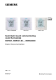
s RDF301, RDF600KN RDF301.50 RDF301.50H Semi-flush mount communicating room thermostats RDF301, RDF301.50..., RDF600KN Basic Documentation Edition: 2.
Contents 1. About this document .............................................................................. 4 1.1 Revision history ......................................................................................... 4 1.2 Reference documents ............................................................................... 4 1.3 1.3.1 1.3.2 1.3.3 Before you start ......................................................................................... 5 Copyright ................................
.11.2 3.11.3 3.11.4 3.11.5 3.11.6 3.11.7 3.11.8 3.11.9 LTE mode ................................................................................................ 52 Zone addressing in LTE mode (in conjunction with Synco) .................... 53 Example of heating and cooling demand zone ....................................... 55 Send heartbeat and receive timeout ....................................................... 56 Startup ..............................................................................
1. About this document 1.1 Revision history Edition Date Changes Section Pages 2.2 June 2014 All All 2.0 1.0 Oct 2012 22 Jun 2010 Added RDF301.50H RDF600KN with window contact and presence detector Update with wiring and protection information New S-mode objects for Economy setpoint Added RDF600… First edition All All 1.2 Reference documents Subject Semi-flush mount room thermostats with KNX communications, RDF301, RDF301.50, RDF600KN KNX Manual Ref [1] [2] [3] [3a] Doc No.
1.3 1.3.1 Before you start Copyright This document may be duplicated and distributed only with the express permission of Siemens, and may be passed only to authorized persons or companies with the required technical knowledge. 1.3.2 Quality assurance This document was prepared with great care.
1.4 Target audience, prerequisites This document assumes that users of the RDF KNX thermostats are familiar with the ETS and/or Synco ACS tools and able to use them. It also presupposes that these users are aware of the specific conditions associated with KNX. In most countries, specific KNX know-how is conveyed through training centers certified by the KNX Association (see www.knx.org/). For reference documentation, see section 1.2. 1.
RDF301 RDF301.50 RDF301.50H RDF600KN Summary 2.1 Types Stock no. S55770-T104 S55770-T105 S55770-T334 S55770-T293 Operating voltage AC 230 V AC 230 V AC 230 V AC 230 V Control outputs 3pos 1) 1 1) 1 1) 1 1) 1 ON/ OFF 1) 2 1) 2 1) 2 1) 2 DC 0..10 V ---- KNX switching groups 3) Hotel: MUR, DND -- Suitable conduit 2) box Product no. 2. rectangular rectangular rectangular round & rectangular 1) Selectable: ON/OFF or 3-position. 2) Rectangular conduit box e.g. ARG71.
Features • • • • • • Type of mounting / suitable conduit boxes • RDF600KN Operating modes: Comfort, Economy (Energy Saving) and Protection ON/OFF or 3-position control outputs (relay) Output for 3-speed or 1-speed fan Automatic or manual heating / cooling changeover Backlit display AC 230 V operating voltage • RDF301… Functions for round CEE/VDE conduit box, with min 60 mm diameter, min 40 mm depth or recessed rectangular CEE/VDE conduit box with 60.
2.4 Integration via KNX bus The RDF room thermostats can be integrated as follows: • Integration into Synco 700 system via LTE mode (easy engineering). • Integration into Synco living via group addressing (ETS). • Integration into Desigo and Apogee via group addressing (ETS) or individual addressing. • Integration into third-party systems via group addressing (ETS). The following KNX functions are available: • Central time program and setpoints, e.g. when using the RMB795 central control unit.
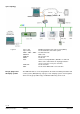
Synco topology Legend: Synco 700 Synco living RDG..., RDF…, RDU… OZW772 RMZ792 QAW... ACS RXB, RXL QAX Desigo, Apogee and third-party systems Building automation and control system (BACS) Room automation and control system Room thermostats Web server Bus operator unit Room unit Service tool using OCI700.1 (OCI700.
2.5 Equipment combinations Description ON/OFF actuators Product no. Data sheet Cable temperature sensor or changeover sensor QAH11.1 1840 Room temperature sensor QAA32 1747 Condensation monitor QXA2601 / QXA2602 / QXA2603 / AQX2604 3302 Electromotoric ON/OFF actuator SFA21... 4863 Electromotoric ON/OFF valve and actuator MVI… / MXI… 4867 SUA… 4832 STA23... 4884 STP23... 4884 SSA31... 4893 SSC31 4895 SSP31… 4864 SSB31... 4891 SSD31...
2.6 Accessories Description Product no / SSN Changeover mounting kit (50 pcs/package) Plastic mounting bracket for semi-flushmount thermostats RDF301... for increasing the headroom in the conduit box by 10mm Conduit box for semi-flush mounted thermostat RDF301... ARG86.3 Data sheet N3009 ARG70.
3. Functions 3.1 Temperature control General note: Parameters Setting of the control parameters (P01, etc., mentioned throughout the document) is described in section 3.13. Temperature control The thermostat acquires the room temperature via built-in sensor, external room temperature sensor (QAA32), or external return air temperature sensor (QAH11.1), and maintains the setpoint by delivering actuator control commands to heating and/or cooling equipment.
3.2 Operating modes The thermostat's operating mode can be influenced in different ways (see below). Specific heating and cooling setpoints are assigned to each operating mode. K NX R The thermostat sends the effective room operating mode on the bus. Room operating mode: State The following operating modes are available: Auto Timer In Auto Timer mode the room operating mode is commanded via bus.
3.2.1 Source for change of operating mode ACS Source Local operation via operating mode button Bus command K NX R Room op. mode The operating mode can be influenced by different interventions.
Operating mode via bus The operating mode can be changed via bus. Time schedule via bus Temporary extended Comfort mode via operating mode button The operating mode can be temporarily set from Economy to Comfort by pressing the operating mode button, if... – Economy was sent via bus – extended Comfort period >0 (parameter P68) The last intervention wins, either locally or via bus. The operating mode sent via bus can be overridden by all other interventions.
Operating mode switchover contact (window contact) (RDF301…) The thermostat can be forced into Economy mode (e.g. when a window is opened, when a presence detector signals "no one present", when the keycard of a hotel room is withdrawn, etc). The contact can be connected to multifunctional input X1, X2. Set parameter P38, P40 to 3. P02 is not relevant. User operations are ineffective and "OFF" is displayed if the operating mode switch over contact is active.
Temporary timer to extend the Comfort mode Comfort mode can be temporarily extended (e.g. working after business hour or on weekends) when the thermostat is in Economy mode. The operating mode button switches the operating mode back to Comfort for the period preset in P68. Press the operating mode button again to stop the timer. The following conditions must be fulfilled: • mode selection via operating mode button is set to "Protection-Auto" (P02 = 1) and the time schedule via bus is Economy.
Example 1 (RDF301…) Operating mode switchover In room 1, the window is opened briefly, once in the morning, once in late afternoon and once at night (1). Only the opening in the morning has a direct impact on the effective room operating mode. During lunch break, the time schedule changes to Precomfort. The mode remains in Comfort as set by parameter "Transformation Precomfort" (P88 = 1).
Example 2 (RDF301…) Interaction of user operation (operating mode button) and central time schedule In room 2, the window is opened briefly, once in the morning and once at night (1). Only the opening in the morning has a direct impact on the effective room operating mode. With the operating mode button, the operating mode can be changed between OFF and Auto or temporary Comfort extension respectively.
Example 3 (RDF600…) Application with "Window Contact", "Presence Detector" and central time schedule In room 3 operating mode Comfort is possible between 6:00 and 20:00, based on time schedule or occupancy period. Outside this time the operating mode remains in Protection. • • • • • • • • • Time schedule Room operating mode At 6:00 the central set the operating mode to Economy. (1) In the morning, as soon as the presence is detected (8:00 – 12:00), the operating mode will be switched to Comfort.
3.3 3.3.1 Comfort mode Room temperature setpoints Description The factory setting for the Comfort basic setpoint is 21 °C and can be changed in the thermostat’s EEPROM via parameter P08 or via bus with communication object "Comfort basic setpoint". The last intervention always wins. The Comfort setpoint can be adjusted via the +/- buttons, or via bus from a remote device like a touch panel, operating unit, etc. The last intervention always wins.
Economy mode Use control parameters P11 and P12 to adjust the Economy mode setpoints. The heating setpoint is factory-set to 15 °C, and the cooling setpoint to 30 °C. Protection mode Use control parameters P65 and P66 to adjust the Protection mode setpoints. The heating setpoint is factory-set to 8 °C (frost protection) and to OFF for cooling. Caution If a setpoint (Economy or Protection) is set to OFF, the thermostat does not control the room temperature in the corresponding mode (heating or cooling).
3.3.
General notes: • The supported communication objects are different in LTE mode and S-mode. • Changes via the local HMI or via tool have the same priority (last always wins). • Setting the Comfort basic setpoint will reset the runtime Comfort setpoint to the basic setpoint. Notes on setpoint adjustment (LTE mode with Synco only) • Central setpoint shift is used for summer / winter compensation in particular. • Setpoint shift does not affect the setpoints stored in parameters P08, P11, P12, P33.
3.4 Applications overview The thermostats support the following applications, which can be configured using the DIP switches inside the front panel of the unit or a commissioning tool. Remote configuration All DIP switches need to be set to OFF (remote configuration, factory setting) to select an application via commissioning tool. Remote configuration, via commissioning tool (factory set) • Synco ACS • ETS DIP switches ON 1 2 3 The tools provide the applications described in section 3.4.
3.4.
3.4.
3.5 Additional functions Heating / cooling changeover via bus The heating / cooling changeover information can be received via bus. This is only possible if the control sequence is set to automatic heating / cooling changeover (parameter P01 = 3) and no local input X1, X2 is assigned with this function. K NX In the absence of the required information (e.g. due to problems with data communication, power failure, etc.), the thermostat operates in the last valid room operating mode (heating or cooling).
Purge function The changeover sensor ensures changeover from heating to cooling mode based on the acquired water temperature. We recommend activating the "Purge" function (parameter P50) with 2-port valves. This function ensures correct acquisition of the medium temperature even if the 2-port valve is closed for an extended period of time. The valve is then opened for 1 to 5 minutes (adjustable) at 2-hour intervals during off hours.
The table below shows the relation between parameter, temperature source and temperature display: OFF OFF 10...50 ˚C External temp. sensor available No Yes No Source for display of room temperature Built-in sensor External temp. sensor Built-in sensor 10…50 ˚C Yes Built-in sensor Parameter P51 Output control according to Built-in sensor External temp. sensor Built-in sensor Built-in sensor + limit by external sensor Floor temp.
3.6 Control sequences 3.6.1 Sequences overview (setting via parameter P01) The main control sequence (i.e. the water coil sequence of the fan coil unit) can be set via parameter P01. The following sequences can be activated in the thermostats (each without or with auxiliary heating). The available sequences depend on the application (selected via DIP switch, see section 3.4). Parameter P01 = 0 P01 = 1 P01 = 2 P01 = 3 P01 = 4 T Sequence T °C Heating T °C Cooling *) 2-pipe with el.
3.6.2 K NX Application mode The behavior of the thermostat can be influenced by a building automation and control system (BACS) via bus with the command "Application mode". With this signal, cooling and/or heating activity can be enabled or disabled. Application mode is supported in LTE mode and S-mode.
ACS Heating OR cooling The state (heating or cooling) of the thermostat can be monitored with the ACS tool (diagnostic value "Control sequence"). The last active mode is displayed when the thermostat is in the dead zone or temperature control is disabled. With a 2 pipe application, the control sequence state is determined by the application mode (see section 3.6.
3.6.3 2-pipe fan coil unit On 2-pipe applications, the thermostat controls a valve in heating / cooling mode with changeover (automatically or manually), heating only, or cooling only. Cooling only is factory-set (P01 = 1). ON/OFF control The diagrams below show the control sequence for 2-position control.
3.6.4 2-pipe fan coil unit with electric heater Heating or cooling with auxiliary heater On 2-pipe applications with electric heater, the thermostat controls a valve in heating / cooling mode with changeover, heating only, or cooling only plus an auxiliary electric heater. Cooling only is factory-set (P01 = 1) with enabled electric heater (P13). Electric heating, active in cooling mode In cooling mode, the valve receives an OPEN command if the acquired temperature is above the setpoint.
ON/OFF control The diagrams below show the control sequence for 2-position. Heating mode Cooling mode (automatic changeover = heating or heating only) (man. / auto.
3.6.5 4-pipe fan coil unit Heating and cooling On 4-pipe applications, the thermostat controls 2 valves in heating and cooling mode, heating / cooling mode by manual selection, or heating and cooling mode with changeover. Heating and cooling mode (P01 = 4) is factory-set. 4-pipe application with manual changeover The heating or cooling output can be released via operating mode button if parameter P01 is set to Manual (P01 = 2).
ON/OFF control The diagrams below show the control sequence for 2-position control. Heating mode with manual selection (P01 = 2) Y1 3076D13 Y 3076D01 Y Cooling mode with manual selection (P01 = 2) Y2 1 1 w w ½ SDH T[°C] 0 T[°C] 0 ½ SDC ½ SDH ½ SDC Heating and cooling mode (P01 = 04) Y1 Y2 ½ xdz ½ xdz 3076D11 Y 1 w 0 ½ SDC ½ SDH Note: T[°C] ½ SDC ½ SDH T[°C] Room temperature w Room temperature setpoint Y1 Control command "Valve" or "Comp.
3.6.7 Compressor applications For compressor applications, • set the corresponding basic application • disable the fan (P52) or set the fan speed (P53) The following applications are available: Application for compressor Set basic application 1-stage compressor for heating or cooling 1-stage compressor and electric heater (for cooling only: disable electric heater via P13) 1-stage compressor for heating and cooling 2-pipe See section 3.6.
3.6.8 2-pipe applications Setpoints and sequences On changeover applications, the Comfort setpoints for heating and cooling sequence are the same (w). On 2-pipe applications with electric heater, the Comfort setpoint is either at the first heating sequence (in heating mode) or at the cooling sequence (in cooling mode). The setpoints for Economy and Protection mode are below the Comfort setpoints (heating) and above the Comfort setpoints (cooling).
4-pipe applications On 4-pipe applications, the Comfort setpoint (w) is in the middle of the dead zone, between the heating and cooling sequence. The dead zone can be adjusted via parameter P33. If manual changeover is selected, then either the cooling sequence or the heating sequence is released. In this case, the Comfort setpoint is at the selected heating or cooling sequence.
3.7 Control outputs 3.7.1 Overview of control outputs Overview Different control output signals are available. They need to be defined during commissioning (see below). Control output Product no. RDF301, RDF301.50, RDF301.50H, RDF600KN 2-position Y11, Y21 (2 x SPST) 2-position PWM 3-position --- Y11, Y21 *) (1 x / ) DC 0…10 V --- *) Only on 2-pipe application Note: ON/OFF control signal (2-position) In the ACS tool, Y11 and Y21 are called Y1 and Y2.
Synchronization 1. When the thermostat is powered up, a closing command for the actuator running time + 150% is provided to ensure that the actuator fully closes and synchronizes to the control algorithm. 2. When the thermostat calculates the positions "fully close" or "fully open", the actuator's running time is extended + 150% to ensure the right actuator position is synchronized to the control algorithm. 3.
3.8 Fan control The fan operates in automatic mode or at the selected speed with manual mode. In automatic mode, the fan speed depends on the setpoint and the current room temperature. When the room temperature reaches the setpoint, the control valve closes and the fan switches off or stays at fan speed 1 according to the setting of parameters P15 (fan stage in dead zone Comfort on RDF600KN) and P60 (fan kick).
Y xdz 1 0 w SDH T[°C] SDC Q Q3 Cool Room temperature w Q Room temperature setpoint Fan speed Y Control command "Valve" SDH Switching differential "Heating" SDC Switching differential "Cooling" Xdz Dead zone XpHFan Switching range for fan "Heating" XpCFan Switching range for fan "Cooling" Q2 Q1 w SDH/SDC [K] XpHFan/XpCFan [K] 0.5 2 T[°C] XpCFan XpHFan Look-up table with ON/OFF control T[°C] 1.0 3 1.5 4 2.0 5 2.5 6 3.0 7 3.5 8 4.0 9 >4.
Fan operation in dead zone P15, Comfort mode (RDF600KN) Via parameter P15 in "Service Level", the fan speed in the dead zone (in Comfort mode) can be set according to customer preference. The following options are available: • Fan does not run in the dead zone (P15=0), • Fan runs at low speed in Heating and Cooling mode (P15=1) • Fan runs at low speed in Cooling mode only (P15=2).
Fan start delay (RDF600KN) To let the heating / cooling coil reach its temperature, the fan start can be delayed by a time period set via parameter P67. 31 81 D23 Y 1 0 T Q P67 T Note: This function (via parameter P67) is not implemented into RDF600KN SW version < V1.8. 48 / 92 Siemens Building Technologies RDF301, RDF301.50...
3.9 Multifunctional input, digital input The thermostat has 2 multifunctional inputs X1 and X2. An NTC type sensor like the QAH11.1 (AI, analog input) or a switch (DI, digital input) can be connected to the input terminals. The functionality of the inputs can be configured via parameters P38 + P39 for X1 and P40 + P41 for X2. K NX The current temperature or state of the inputs X1/X2 is available on bus for monitoring purposes.
# 5 K NX Function of input Enable electric heater 6 Fault R 7 Monitor input (Digital) R 8 Monitor input (Temperature) 10 Presence detector 1) (RDF600KN) R Fault information K NX X1, X2 (Digital) K NX X1, X2 (Temp.) K NX Digital input to enable / disable the electric heater via remote control. Type X1/X2 DI Enable electric heater is also possible via bus. In this case, the function must not be assigned to any local input X1, X2. See also section 3.6.
3.10 Handling faults Temperature out of range When the room temperature is outside the measuring range, i.e. above 49 °C or below 0 °C, the limiting temperatures blink, e.g. "0 °C" or "49 °C". In addition, the heating output is activated if the current setpoint is not set to "OFF", the thermostat is in heating mode and the temperature is below 0 °C. For all other cases, no output is activated. The thermostat resumes Comfort mode after the temperature returns to within the measuring range.
3.11 KNX communications The RDF KNX thermostats support communications as per the KNX specification. S-mode Standard mode; engineering via group addresses. LTE mode Logical Tag Extended mode, for easy engineering, is used in conjunction with Synco. 3.11.1 S-mode This mode corresponds to KNX communications. Connections are established via ETS by assigning communication objects to group addresses. 3.11.2 LTE mode LTE mode was specifically designed to simplify engineering.
• For a detailed description of KNX (topology, bus supply, function and setting of LTE zones, filter tables, etc.), see "Communication via the KNX bus for Synco 700, 900 and RXB/RXL, Basic Documentation" [6]. • LTE mode data points and settings are described in the Synco Application Manual [12]. • To engineer and commission a specific system, use the Synco700 planning and commissioning protocol (XLS table in HIT, [7]). Engineering and commissioning 3.11.
The zones to be defined are as follows: Geographical zone (space zone) Zone in which an RDF KNX thermostat is physically located. Other room-specific devices may also be located in this zone. (Apartment . Room . Subzone) Apartment = ---, 1...126 Room = ---, 1...63 Subzone = fix 1 Information exchanged in this zone is related specifically to the device like operating mode, setpoints, room temperature, etc. The designations "Apartment", "Room" and "Subzone" do not need to be taken literally.
3.11.4 Example of heating and cooling demand zone The building is equipped with Synco controls on the generation side and RDF / RDG thermostats on the room side. Konnex TP1 RMH760 Controller 1 RMB795 Controller 3 Controller 2 RDF... Controller 4 RDU... Controller 5 RDG...
3.11.5 Send heartbeat and receive timeout In a KNX network, S-mode and LTE mode communication objects can be exchanged between individual devices. The Receive timeout defines the period of time within which all the communication objects requested from a device must have been received at least once. If a communication object is not received within this period, a predefined value is used.
3.11.8 Fault function on KNX If a fault occurs (e.g. digital fault input, dew point, communication configuration, etc.) then a fault will be sent on the bus. An RDF thermostat listens on the bus and sends its fault when the fault has the highest alarm priority. This ensures that the management station does not miss any alarms. If alarms occur at the same time, the alarm with the highest priority will be first displayed and sent on the bus.
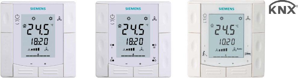
3.11.9 KNX switching groups (RDF301.50, RDF301.50H only) K NX Light and blinds as well as scenes are operated via switching groups. R The communication objects of the buttons need to be bound to a corresponding KNX actuator module. Buttons 5 1 3 2 4 RDF301.50 1, 2 Buttons of switching group left (1). 3, 4 Buttons of switching group right (2). 5 Display for indication while pressing buttons. RDF301.50H 1, 2 Button label: Make Up Room (MUR), ON/OFF. 3, 4 Button label: Do Not Disturb (DND), ON/OFF.
Parameters per switching group # Parameter Function left / right buttons Parameters per single button # Function Parameter 1 Switch "ON/OFF" functions 0 1 2 3 4 Parameter value Inactive (factory setting) Switch Dim Shutter Scene 0 Parameter value Child Parameter: Top: ON; bottom: OFF 1 Operating switching groups Note: 2 "ON/OFF" functions Function top button: Toggle (ON/OFF) 0 ON 1 2 OFF Function bottom button: Toggle (ON/OFF) 0 ON 1 2 OFF # Function Parameter 4 Scene Scene number top
3.12 Communication objects (S-mode) 3.12.
3.12.2 Description of communication objects Obj 1 Object name System time Function Type/ length Flags Time and 19.001 CWU date 8 Byte System time for display on the room thermostat. See parameter P07 (3 or 4) 3 Time of day Time and 10.001 CWU date 3 Byte Another object for receiving the time of day for display on the room thermostat. See parameter P07 (3 or 4) 4 Fault information Alarm 219.001 CT Info 6 Byte Common alarm output.
Obj Object name Function Type/ length Flags An electric heater can be disabled with this communication object (e.g. to meet tariff regulations). The same function is also available via local multifunctional input X1/X2 (parameter P38, P40). Only one input source must be used, either local input X1/X2 or KNX bus. 30 Heating / cooling Heat / 1.100 CWU changeover Cool 1 bit Changeover information transmitted via bus. Default: Current mode before power down.
Obj Object name Function Type/ length Flags The "Scene (8-bit)" function is used to change the characteristics of a preset scene, i.e. brightness levels and switching states of a group within a scene, without using the ETS. For scene control, short and long (<1 s / > 3 s) pressing on the buttons are distinguished. On a short press, a telegram is sent to recall the corresponding scene. On a long press, a telegram is sent to save the corresponding scene.
3.13 Communication objects (LTE-mode) RDF Geographical zone A.R.S Room operating mode: Time switch (Time switch zone) X.1.1 / X.Y.1 Application mode Room operating mode: Preselection Geographical zone A.R.S X.Y.1 Room temperature output Comfort setpoint Setpoints heating Setpoints cooling Fan speed Setpoint shift heating Setpoint shift cooling Heat distr. zone Heating coil energy demand heating coil Heating/Cooling changeover Ref. distr. zone cooling coil Cooling coil energy demand Heat distr.
3.14 Control parameters A number of control parameters can be readjusted to optimize control performance. This can be done on the thermostat via HMI or via commissioning / operating tool. These parameters can also be set during operation without opening the unit. In the event of a power failure, all control parameter settings are retained, see page 51. The control parameters are assigned to 2 levels: • "Service level", and • "Expert level" including communications, diagnostics and test.
3.14.2 Parameter setting / download via tool Control parameters can be adjusted via bus either by parameter download during commissioning or during normal operation with a tool like ACS. ACS With the ACS tool, the parameters can be changed… – during commissioning via parameter download (all parameters) – during normal operation via Popcard (most of the parameters).
P01 Range 2-pipe: 1 = Cooling only 0 = Heating only 1 = Cooling only 2 = H/C changeover manual 3 = H/C changeover auto 4 = Heating and Cooling 1 = Auto – Protection 2 = Auto - Comfort - Economy – Protection C = ° Celsius F = ° Fahrenheit – 3 ... 3 K 0 = Room temperature 1 = Setpoint 0 = --- (No display) 1 = °C and °F 2 = Outside temperature (via bus) 3 = Time of day (12h) (via bus) 4 = Time of day (24h) (via bus) 5 ... 40 °C 5 ... 40 °C 5 ... 40 °C OFF, 5 ...
Range RDF600KN 2K 0.5 … 6 K 1K 0.5 … 6 K 2K 2K 0.5 … 5 K 0.5 … 5 K Appl. Appl. 5 min 45 min 16 °C 0…10 min 0...120 min 10…25 °C x x P46 P46 P38, P40 28 °C 27…40 °C P38, P40 3 = Op mode contact, window contact P40 P46 Dependencies Factory setting Parameter Name RDF301.. 3.14.
Range RDF301.. RDF600KN P52 P52, Appl. P52, P53, DIP P52, P53, DIP P52, P53, DIP P52 Dependencies Factory setting Parameter Name Expert level P52 Fan control 1 P53 Fan speeds 3-speed P54 P55 Fan overrun time Fan speed switching point high Fan speed switching point med Fan speed switching point low Fan start kick 60 sec 100% 0 = Disabled 1 = Enabled 2 = Heating only 3 = Cooling only 1 = 1-speed 2 = 3-speed 0...360 sec 80...100% 65% 30..75% 10% 1...
Range Dependencies Parameter Name Diagnostics & test d01 Application number d02 X1 state d03 X2 state d05 Test mode for checking the Y11/Y21 actuator's running direction 3) 3) NONE = (No application) 2P = 2-pipe 2P3P = 2-pipe 3-position 2PEH = 2-pipe with electric heater 4P = 4-pipe "---" = function not selected 0 = Not activated (for DI) 1 = Activated (DI) 0…49 °C = Current temp.
4. Handling 4.1 Mounting and installation Mount the room thermostat on the conduit box. Do not mount on a wall in niches or bookshelves, behind curtains, above or near heat sources, or exposed to direct solar radiation. Mount about 1.5 m above the floor. Mounting / dismounting • Mount the room thermostat in a clean, dry indoor place without direct airflow from a heating / cooling device, and not exposed to dripping or splash water. • RDF301...
4.2 Applications Commissioning The room thermostats are delivered with a fixed set of applications. Select and activate the relevant application during commissioning using one of the following tools: – Local DIP switch and HMI – Synco ACS – ETS DIP switches Set the DIP switches before snapping the front panel to the mounting plate, if you want to select an application via DIP switches.
Control parameters The thermostat's control parameters can be set to ensure optimum performance of the entire system. The parameters can be adjusted using – Local HMI – Synco ACS – ETS Commissioning of switching groups for RDF301.50… is only possible with ETS). The control parameters of the thermostat can be set to ensure optimum performance of the entire system (see section 3.13, control parameters).
4.3 Operation See also Operating Instructions B3171 [2] enclosed with the thermostat. Layout 1 2 1 2 4 4 2 1 5 3 3 RDF301, RDF600KN RDF301.50 5 3 RDF301.50H 1 Operating mode selector 2 Button to change fan operation 3 Buttons to adjust setpoints and control parameters RDF301.50 RDF301.
Display 1 4 2 5 3 7 6 8 6 9 10 1 Operating mode Protection Comfort Economy Auto Timer according to schedule (via bus) 5 Condensation in room (dew point sensor active) 6 Indicates fault or reminder 7 Temporary Comfort mode extension active 2 Displays room temperature, setpoints and control parameters. Symbol indicates current room temperature 8 Additional user information, like outside temperature or time of day from KNX bus.
5. 5.1 Supported KNX tools ETS ETS is an engineering tool. It can be used for the full commissioning of the RDF KNX thermostats. ETS The following functions can be realized with ETS4: – – – – – Define and download the physical address Define and download the application (plant type, control sequence) Set up and download the thermostat's control parameters Download the switching group parameters (RDF301.50) Set up and download group addresses.
The application (plant type) and Control Sequence can be adjusted and downloaded. The control parameters, ([Pxx] description) can also be adjusted and downloaded. Refer to section 3.13. 5.2 ACS ACS Service and Operating tool With the ACS tool, the RDF KNX thermostats can be commissioned (physical address, application, parameters). They can be operated or monitored via bus during normal operation. This Manual does not describe how the physical address is defined.
5.2.1 Parameter settings in ACS In the ACS program, select Plant, then Open to open the plant. To start the parameter settings, select Applications, then Plant engineering…: The application and control parameters can be adjusted and downloaded. Column Line no. contains the parameter number as shown in the parameter table. Refer to section 3.13, control parameters. • 78 / 92 Siemens Building Technologies RDF301, RDF301.50...
5.2.2 Operation and monitoring with ACS In the ACS program, select Plant, then Open to open the plant. To start monitoring and operation, select Applications, then Plant operation. ACS ACS supports parameter settings even during normal operation. Parameter settings in ACS To change a control parameter, select Popcard, then Settings.
Plant diagram in ACS ACS offers plant diagrams for easy monitoring and operation of the thermostat. To start this application, select Applications, then Pant diagram. 80 / 92 Siemens Building Technologies RDF301, RDF301.50...
ACS provides standard plant diagrams for RDF KNX thermostats, which depend on the configuration as follows: • Plant type Application Configuration Application Configuration 2-pipe fan coil unit – Control sequence: No impact (P01 = any) – Fan operation: Not disabled (P52 <> 0) Radiator – Control sequence: Heating only (P01 = 0) – Fan operation: Disabled (P52 = 0) Chilled / heated ceiling – Control sequence: Changeover (P01 = 2,3) – Fan operation: Disabled (P52 = 0) Chilled ceiling – Control sequence: C
5.2.3 Operation and monitoring with OZW772 The OZW772 web server enables users to operate a Synco HVAC system from a remote location – via PC, or from a smart phone – using the HomeControl app. A start page shows the most important data points. A combination of menu / path navigation enables users to access all data points quickly and straightforwardly. The entire installation can be visualized in the form of plant diagrams.
Connection 6.1 Connection terminals L N SELV 3171A01 6. X1 M Q1 Q2 Q3 X2 CE+ CE Y11 N Y21 L, N Q1 Q2 Q3 Y11,Y21 X1, X2 M CE+ CE- Operating voltage AC 230 V Control output "Fan speed 1 AC 230 V" Control output "Fan speed 2 AC 230 V" Control output "Fan speed 3 AC 230 V" Control output "Valve" AC 230 V (NO, for normally closed valves), output for compressor or output for electric heater Multifunctional inputs for temperature sensor (e.g. QAH11.
Application Connection diagrams L AC 230 V F KNX S1 S2 B1 B2 L X1 M CE+ CE- X2 Y21 Y11 N Q1 Q2 Q3 Y1 M1 N 5(2)A max. 5(2)A max. Y1 5(2)A max. Y1 5(2)A max. 4-pipe – Y1 = Heating – Y2 = Cooling 1-stage compressor – C1 = Heating and / or – C2 = Cooling) 1-stage compressor and electric heater N1 M1 Y1 Y1, Y2 E1 C1, C2 F S1, S2 B1, B2 2-pipe, 3-position – Y11 = Open – Y21 = Close 2-pipe and electric heater N1 10 A I II III 2-pipe, 2-position 3171A12 6.2 E1 5(2)A max.
7. Mechanical design 7.1 General The thermostats consist of 2 parts: • Front panel with electronics, operating elements and built-in room temperature sensor. • Mounting base with power electronics. The rear of the mounting base carries the screw terminals. Slide the front panel in the mounting base and snap on. 1 2 2 1 2 1 4 4 3 5 3 RDF301, RDF600KN RDF301.50 5 3 RDF301.50H 1 Operating mode selector 2 Button for fan operation 3 Buttons to adjust setpoints and control parameters RDF301.
7.2 Dimensions Dimensions in mm 86 16 30 80 3076M13_01 14 3076M12 3171M13 86 3076M01 3076M01 86 RDF600KN 86 RDF301... 86 / 92 Siemens Building Technologies RDF301, RDF301.50...
8. Power supply Caution Outputs STOP Note! Caution Inputs KNX bus Technical data Rated voltage AC 230 V Overvoltage category III Frequency 50/60 Hz Power consumption RDF301... Max. 4 VA / 3.0 W RDF600KN Max. 3.5 VA / 1.2 W No internal fuse External preliminary protection with max C 10A circuit breaker Required in all cases Fan control Q1, Q2, Q3-N AC 230 V Rating Min, Max resistive (inductive) Min. 5 mA, Max.
Operational data Switching differential (adjustable) Heating mode Cooling mode Setpoint setting and range Comfort Economy Protection Multifunctional input X1/X2 Input X1 default value (P30) (P31) (P08) (P11-P12) (P65-P66) Input X2 default value (P38) (P40) Built-in room temperature sensor Measuring range Accuracy at 25 °C Temperature calibration range Settings and display resolution Setpoints Current temperature value displayed Environmental conditions Operation Climatic conditions Temperature Humidit
Environmental Compatibility General *) The product environmental declaration CE1T3076xx contains data on environmentally compatible product design and assessments (RoHS compliance, materials composition, packaging, environmental benefit, disposal). Connection terminals Solid wires or prepared stranded wires 2 1 x 0.4…1.5 mm 2 Minimal wiring cross section on min 1.5 mm L, N, Q1, Q2, Q3, Y11, Y21 Housing front color RAL 9003 white Weight without / with packaging RDF301... 0.240 kg / 0.320 kg RDF600KN 0.
Index 1 1-speed fan ........................................................... 46 3 3-position control signal ........................................ 43 3-speed fan ........................................................... 46 A Applications overview ........................................... 26 Auto Timer mode .................................................. 16 Automatic heating / cooling changeover ......... 29, 32 Automatic heating / cooling changeover via bus .. 29 B Basic application ...........
R Radiator applications ............................................ 39 Reload factory settings ......................................... 65 Remote heating / cooling changeover ................. 29 Reset parameters ................................................. 65 S Sensor input .......................................................... 49 Setpoint Comfort mode ......................................... 41 Setpoint Economy mode ...................................... 41 Setpoint limitation ................
Siemens Switzerland Ltd Infrastructure & Cities Sector Building Technologies Division International Headquarters Gubelstrasse 22 CH-6301 Zug Tel. +41 41-724 24 24 Fax +41 41-724 35 22 www.buildingtechnologies.siemens.com 92 / 92 Siemens Building Technologies © 2010 - 2014 Siemens Switzerland Ltd RDF301, RDF301.50...