s RDF301, RDF600KN 3 171 RDF301.50 Semi flush-mount communicating room thermostats RDF301.50H RDF301 RDF301.50.. RDF600KN For 2-pipe, 2-pipe with electrical heater, and 4-pipe fan coil units For use with compressors in DX type equipment • • • • • • • • • • • • • • • KNX bus communications (S-mode and LTE mode) Backlit display 2P / PI / P control Outputs for on/off or 3-position control Outputs for 3-speed or 1-speed fan 2 multifunctional inputs for keycard contact, external sensor, etc.
Additional RDF600KN features: • Independent function for window contact and presence detector Additional RDF301.50 features: • Four buttons to control KNX actuators via KNX S-mode (functions: switching, dimming, blinds control, 8-bit scene) Additional RDF301.50H features: • Four buttons for hotel functions MUR (Make Up Room), DND (Do Not Disturb) via KNX S-mode Type of mounting / suitable conduit boxes: • RDF600KN for round box, with min 60 mm diameter, min 40 mm depth and recessed rectangular box with 60.
• • • • • • • • • • • • • • • Temporary Comfort mode extension. 1- or 3-speed fan control (automatically or manually). Display of current room temperature or setpoint in °C and/or °F. Minimum and maximum limitation of room temperature setpoint. Button lock (automatically and manually).
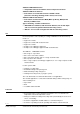
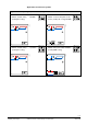
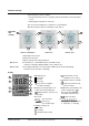
Applications for fan coil systems Application and output signal, DIP switches, diagram ON • 2-pipe fan coil unit (heating or cooling) ON ON/OFF 2 3 1 2 3 2 3 3171D21 3076D20 1 • 2-pipe fan coil unit with el.
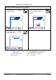
Applications for Universal systems Application and output signal, DIP switches, diagram ON 1 2 3 3191S11 B2 ON/OFF D3 T • Chilled / heated ceiling with electric heater (heating or cooling) ON/OFF B2 1 2 3 2 3 3191S12 • Chilled / heated ceiling (heating or cooling) ON D3 T Y1 Y1 T T B1 B1 YE T N1 T N1 ON ON 1 2 3 • Chilled ceiling and radiator ON/OFF (heating and cooling) 3191S11 B2 3-position D3 T Y1 1 3191S13 • Chilled / heated ceiling (heating or cooling) D3 Y
Applications for heat pump systems Application and output signal, DIP switches, diagram ON 1 2 3 • 1-stage compressor with electric heater (heating or cooling) ON/OFF D3 1 2 3 3181S32 ON/OFF 3181S31 • 1-stage compressor (heating or cooling) ON D3 T T B1 B1 YE T T N1 N1 ON ON/OFF 1 2 3 3181S35 • 1-stage compressor (heating and cooling) D3 T B1 T Key N1 Y1 Heating or heating / cooling valve actuator Y2 Cooling valve actuator YE Electric heater B1 Return air temperature senso
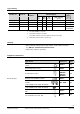
Product no. RDF301 RDF301.50 RDF301.50H RDF600KN Operating voltage Stock no. S55770-T104 S55770-T105 S55770-T334 S55770-T293 AC 230 V AC 230 V AC 230 V AC 230 V Control outputs 3pos 1) 1 1) 1 1) 1 1) 1 ON/ OFF 1) 2 1) 2 1) 2 1) 2 DC 0..10 V ---- 1) Selectable: ON/OFF or 3-position. 2) Rectangular conduit box e.g. ARG71.
3-position actuators Note: Electrical actuator, 3-position (for radiator valve) Electrical actuator, 3-position (for 2- and 3-port valves / V…P45) Electrical actuator, 3-position (for small valve 2,5 mm) Electrical actuator, 3-position (for small valve 5,5 mm) Electrical actuator, 3-position (for small valve 5,5 mm) Electromotoric actuator, 3-position (for valves 5.5 mm) SSA31... 4893 SSC31 4895 SSP31… 4864 SSB31... 4891 SSD31...
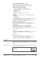
Mechanical design The thermostats consist of 2 parts: • Front panel with electronics, operating elements and built-in room temperature sensor. • Mounting base with power electronics. The rear of the mounting base contains the screw terminals. Slide the front panel in the mounting base and snap on. Operation 1 and settings 2 2 1 2 1 4 5 4 3 3 RDF301, RDF600KN 5 3 RDF301.50 RDF301.50H 1 Operating mode selector 2 Change fan operation 3 Adjust setpoint and control parameters RDF301.50 RDF301.
Engineering notes See the "Reference documentation", page 15 for information on how to engineer the KNX bus (topology, bus repeaters, etc.) and how to select and dimension connecting cables for supply voltage and field devices. Mounting and installation Mount the room thermostat on a conduit box. Do not mount on a wall in niches or bookshelves, behind curtains, above or near heat sources, or exposed to direct solar radiation. Mount about 1.5 m above the floor.
Commissioning notes Applications The room thermostats are delivered with a fixed set of applications. Select and activate the relevant application during commissioning using one of the following tools: − Local DIP switch and HMI − Synco ACS − ETS Set the DIP switches before snapping the front panel to the mounting plate, if you want to select an application via DIP switches. All DIP switches need to be set to "OFF" ("remote configuration"), if you want to select an application via commissioning tool.
Control parameters The thermostat's control parameters can be set to ensure optimum performance of the entire system (see basic documentation P3171). The parameters can be adjusted using − Local HMI − Synco ACS − ETS Control sequence • The control sequence may need to be set via parameter P01 depending on the application. The factory setting for the 2-pipe application is "Cooling only"; and "Heating and Cooling" for the 4-pipe application.
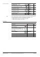
Technical data Power supply Caution Outputs STOP Note! Caution Inputs KNX bus Operational data Rated voltage AC 230 V Overvoltage category III Frequency 50/60 Hz Power consumption RDF301... Max. 4 VA / 3.0 W RDF600KN Max. 3.5 VA / 1.2 W No internal fuse External preliminary protection with max C 10 A circuit breaker Required in all cases AC 230 V Fan control Q1, Q2, Q3-N Min. 5 mA, Max.
Environmental conditions Standards and directives Built-in room temperature sensor Measuring range Accuracy at 25 °C Temperature calibration range Settings and display resolution Setpoints Current temperature value displayed Operation Climatic conditions Temperature Humidity Transport Climatic conditions Temperature Humidity Mechanical conditions Storage Climatic conditions Temperature Humidity EU conformity (CE) Product standards Automatic electric controls for household and similar use Special requireme
Reference documentation Handbook for Home and Building Control - Basic Principles (http://www.knx.org/knx-en/training/books-documentation/knx-associationbooks/index.
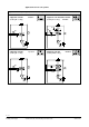
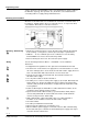
Application L AC 230 V F KNX S1 S2 B1 B2 L X1 M CE+ CE- X2 Y21 Y11 N Q1 Q2 Q3 Y1 M1 N 5(2)A max. 5(2)A max. Y1 5(2)A max. CE+ CEY1 5(2)A max. 4-pipe − Y1 = Heating − Y2 = Cooling 1-stage compressor − C1 = Heating and / or − C2 = Cooling) 1-stage compressor and electric heater N1 M1 Y1 Y1, Y2 E1 C1, C2 F S1, S2 B1, B2 2-pipe, 3-position − Y11 = Open − Y21 = Close 2-pipe and electric heater N1 10 A I II III 2-pipe, 2-position 3171A12 Connection diagrams E1 5(2)A max.
Dimensions Dimensions in mm RDF600KN 3076M01 86 RDF301... 14 30 80 3076M13_01 16 3076M12 3171M13 86 © 2009 - 2014 Siemens Switzerland Ltd Subject to change 17 / 17 Siemens Building Technologies RDF301, RDF301.50...