3 RDF302, RDF302.B 079 RDF302/VB RDF302 Flush-mounted room RDF302.
Use Room temperature control (heating or cooling) in individual rooms and zones by means of: 2-pipe fan coil units 2-pipe fan coil units with electrical heater 4-pipe fan coil units Compressors in DX-type equipment Compressors in DX-type equipment with electrical heater The RDF302, RDF302/VB and RDF302.
Floor heating temperature limit Reload factory settings for commissioning and control parameters RS 485 Modbus (terminals +, - and REF) for communication with Modbus compatible devices Display of outdoor temperature or time of day via Modbus Applications The thermostats support the following applications, which can be configured using the DIP switches inside the front panel of the unit or a Modbus commissioning tool.
Applications for fan coil systems *) Application and output signal, DIP switches, diagram 2-pipe fan coil unit (heating or cooling) ON/OFF 2-pipe fan coil unit with el.
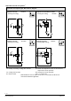
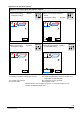
Applications for Universal systems *) Application and output signal, DIP switches, diagram ON/OFF ON 3 D3 T B2 D3 T 1 2 3 V1 V1 T Chilled / heated ceiling (heating or cooling) T T B1 B1 E1 N1 3-position ON T D3 T V1 N1 Chilled ceiling and radiator ON/OFF (heating and cooling) 2 3 ON 1 3191S11 1 B2 ON 2 3 3191S13 B2 2 3191S11 1 Chilled / heated ceiling with electric heater (heating or cooling) ON/OFF 3191S12 Chilled / heated ceiling (heating or cooling) D3 V2 T
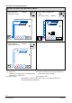
Applications for heat pump systems *) Application and output signal, DIP switches, diagram ON ON/OFF 2 3 3181S31 1 D3 ON 1-stage compressor with electric heater (heating or cooling) ON/OFF 1 2 3 3181S32 1-stage compressor (heating or cooling) D3 T T B1 B1 E1 T 1-stage compressor (heating and cooling) N1 T N1 ON ON/OFF 2 3 3181S35 1 D3 T B1 T N1 B1 Return air temperature sensor or external room N1 Thermostat Terminal Y11: Heating (H&C) or Heating/Cooling temperature sensor
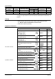
Type summary Product number RDF302 RDF302/VB RDF302.B Stock number Operating voltage Control outputs Suitable conduit box Color 3-pos ON/OFF S55770-T238 AC 230 V 1 1) 2 1) square White 1) S55770-T428 AC 230 V 1 2 1) square Black S55770-T416 AC 230 V 1 1) 2 1) square White 1) Selectable: ON/OFF or 3-position For input and output difference between RDF302, RDF302/VB and RDF302.B, see page 15. Ordering · When ordering, indicate both product number / SSN number and name: E.g.
Electrical actuator, 3-position (for small valves 5.5 mm) Electromotoric actuator, 3-position (for small valves 5.5 mm) Note: SSD31... 4861 SQS35… 4573 For the maximal number of actuators in parallel, refer to information in the data sheets of the selected actuators and to this list, depending on which value is lower: · Parallel operation of max 6 SS… actuators (3-pos) is possible. · Parallel operation of max 10 ON / OFF actuators is possible. · Parallel operation of SQS35 is not possible.
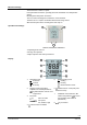
Mechanical design The thermostats consist of 2 parts: Front panel with electronics, operating elements and built-in room temperature sensor. Mounting base with power electronics. The rear of the mounting base contains the screw terminals. The base fits on a square conduit box with 60.3 mm fixing centers. Slide the front panel in the mounting base and snap on. Operation and settings 1 2 3 RDF302, RDF302/VB, RDF302.
Engineering notes Device address The device address of each RDF302… was assigned to “1“ (factory setting). If necessary, engineer/installer can change the address value through the parameter P81. Baud rate The Baud rate is selectable. Four options, 4800 bps, 9600 bps, 19200 bps and 38400 bps, are available for the RDF302… adapting into the Modbus network (19200 bps is default). Parity The parity can be set to none, odd or even (even is default).
Cables of SELV inputs X1-M / X2-M: Use cables with min 230 V insulation, as the conduit box carries AC 230 V mains voltage. Inputs X1-M or X2-M: Several switches (e.g. summer / winter switch) may be connected in parallel. Consider overall maximum contact sensing current for switch rating. Isolate the cables of Modbus communication input +, - and REF for 230 V. No cables provided with a metal sheild. Disconnect from supply before opening the cover.
Disposal The device is considered electrical and electronic equipment for disposal in terms of the applicable European Directive and may not be disposed of as domestic garbage. · Dispose of the device through channels provided for this purpose. · Comply with all local and currently applicable laws and regulations.
Technical data Power supply Outputs Rated voltage AC 230 V Frequency 50/60 Hz Power consumption Max. 7 VA / 3.7 W No internal fuse! Caution External preliminary protection with max C 10 A circuit breaker required in all cases. Fan control Q1, Q2, Q3-N AC 230 V Rating 5 mA…5(2) A Fans must NOT be connected in parallel! Connect one fan directly, for additional fans, one STOP Note! relay for each speed. Caution Inputs Modbus Control output Y11-N / Y21-N (N.O.) AC 230 V Rating Max.
Operational data Environmental conditions Standards and directives Environmental compatibility General Switching differential, adjustable 2 K (0.5...6 K) Heating mode (P30) 1 K (0.5...6 K) Cooling mode (P31) Setpoint setting and range 21 °C (5...40 °C) Comfort (P08) 15 °C / 30 °C (OFF, 5...40 °C) Economy (P11-P12) 8 °C / OFF (OFF, 5...40 °C) Protection (P11-P12) **) Multifunctional input X1/X2 Selectable 0...8 Input X1 default value (P38) 3 (Op.
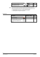
Connection terminals L, N Q1 Q2 Q3 Y11,Y21 Operating voltage AC 230 V Control output “Fan speed 1 AC 230 V” Control output “Fan speed 2 AC 230 V” Control output “Fan speed 3 AC 230 V” Control output “Valve” AC 230 V (N.O., for normally closed valves), output for compressor or output for electrical heater X1, X2 1) Multifunctional input for temperature sensor (e.g. QAH11.
Dimensions (mm) 16 / 18 Siemens Smart Infrastructure RDF302… Flush-mounted room thermostats with RS485 Modbus communications CE1N3079en 2020-02-21
/ 18 Siemens Smart Infrastructure RDF302… Flush-mounted room thermostats with RS485 Modbus communications CE1N3079en 2020-02-21
Issued by Siemens Switzerland Ltd Smart Infrastructure Global Headquarters Theilerstrasse 1a CH-6300 Zug Tel. +41 58 724 2424 www.siemens.com/buildingtechnologies © Siemens Switzerland Ltd, 2011 - 2020 Technical specifications and availability subject to change without notice.