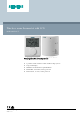
Wireless room thermostat with LCD RDH100RF/SET Non-programmable, for heating systems ● ● ● ● ● A6V10954418_en--_g 2020-11-19 2-position or PID control to switch on/off heating systems Large LCD display Minimum and maximum setpoint limitation RDH100RF, transmitter, battery powered RCR100/433, receiver, mains powered Smart Infrastructure
Use The device comprises of 1 RDH100RF (transmitter) and 1 RCR100/433 (receiver), is used to control the room temperature in heating systems.
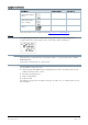
Control behaviour (P01) The factory setting for control is “PID slow”, ideal for most heating systems.
Commissioning notes Parameter list Parameter Description Factory setting Setting range Remark P01 Control behavior PID slow (4) 0 = 2P, 1.0 K 1 = 2P, 0.5 K 2 = PID fast 4 = PID slow P02 Maximum temperature range 30 °C P03…30 °C Limit of comfort and economy setpoint P03 Minimum temperature range 5 °C 5 °C…P02 Limit of comfort and economy setpoint End Exit parameter setting Parameter setting The parameter setting remains in non-volatile memory and is not erased when the battery is removed.
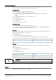
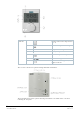
Equipment combinations Description Product number Data sheet *) Electrothermal actuator (for radiator valves) STA23.. 4884 Electrothermal actuator (for small valves 2.5mm) STP23.. 4884 Electromotoric actuator SFA21.. 4863 *) The documents can be downloaded from http://siemens.com/bt/download. Display The digital display shows the current room temperature and the comfort temperature setpoint. When the heating output is active, the triangle symbol is displayed.
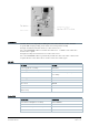
Elements 1 Display of the room temperature in °C / °F 2 Indicates a request for heating 3 Temperature setting knob 4 Battery compartment 5 Comfort temperature setpoint 6 RF TEST Indicates RF signal test Indicates low battery power; replace batteries 7 The receiver is located in a plastic housing with LEDs and buttons. The transmitter is located in a plastic housing. Two buttons are visible on the rear when removing the baseplate.
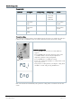
OVERRIDE Override allows for temporarily overriding the active value from the sender. Override responds differently depending on the radio connection (normal or fault). Example A: Normal connection between sender and receiver Press the OVERRIDE button to overwrite the value for ca. 14 minutes. The value then returns to the setpoint. Example B: Faulty connection between sender and receiver Press the OVERRIDE button to permanently override the value.
Notes Mounting When mounting the transmitter, attach the baseplate first. You need to mount the transmitter on a flat wall. (For details, refer to the separate mounting instructions A6V10974421.) The transmitter comes with a fold-out stand and may be used as a “mobile” device. Mounting the receiver does not require a baseplate. Connect the electrical connections first and then fit and secure the receiver in compliance with local regulations.
Disposal The device is considered an electronic device for disposal in accordance with the European Guidelines and may not be disposed of as domestic garbage. ● Dispose of the device through channels provided for this purpose. ● Comply with all local and currently applicable laws and regulations. ● Dispose of empty batteries in designated collection points.
Technical data Power supply Operating voltage DC 3 V (2 x 1.5 V AA alkaline batteries) Battery life >1 year (with AA alkaline batteries) Sensor inputs Internal thermistor 10 kΩ ± 1% at 25 °C Radio frequency Frequency band ISM 433MHZ Maximum radio-frequency power 4.
Standards, directives and approvals EU conformity (CE) A6V101123354 *) RCM conformity to EMC emission standard A6V101123355 *) Safety class III as per EN 60950-1 Pollution degree 2 Degree of protection of housing IP20 Environmental compatibility The product environmental declaration (A6V101123359 *) contains data on environmentally compatible product design and assessments (RoHS compliance, materials composition, packaging, environmental benefit, disposal).
Switching outputs (LX, L1, L2) Relay contacts Switching voltage Max. AC 250 V; Min. AC 24 V Switching current Max. 8 A res., 3 A ind. At AC 250 V Min. 10 mA Contact life at AC 250 V At 5 A res. 1 x 10⁵ cycles (guide value) Insulating strength Between relay contacts and coil AC 5,000 V Between relay contacts (same pole) AC 1,000 V Electrical connections Connections terminals (via baseplate) For solid wires For stranded wires Screw terminals 2 x 1.5 mm2 1 x 2.5 mm2(min. 0.
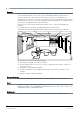
Connection diagram L Live, AC 230 V Lx Live, AC 24…250 V L1 N.O. contact, AC 24…250 V / 8 (3) A L2 N.C.
F1 Thermal reset limit thermostat N1 Room temperature controller RDH100RF (Transmitter) F2 Safety limit thermostat N2 RCR100/433 (Receiver) M1 Circulating pump Y1 3-port valve with manual adjustment Y2 Magnetic valve 14 Siemens Smart Infrastructure Datasheet A6V10954418_en--_g 2020-11-19
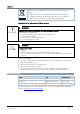
Dimensions [mm] Room temperature controller Room temperature controller mounting plate 15 Siemens Smart Infrastructure Datasheet A6V10954418_en--_g 2020-11-19
Room temperature receiver with mounting plate Product history Index Date ≥C June 2018 ● Z, A March 1) Changes Add new function min/max temperature limitation, selectable control behavior and parameter settings. First release. 2017 1) Product index can be found next to the production date on the rear of the device "YYMMDDX". 16 Issued by Siemens Switzerland Ltd Smart Infrastructure Global Headquarters Theilerstrasse 1a CH-6300 Zug Tel. +41 58 724 2424 www.siemens.